This thread has been locked.

If you have a related question, please click the "Ask a related question" button in the top right corner. The newly created question will be automatically linked to this question.

I2C Initialization Problem on OMAP-L138 Experimenter SOM

Guru 15580 points


I am using the Logic SOM-M1 on a custom board using the Logic BSL drivers. During the initilzation process of the I2C1 the following code is used (from evmomapl138_i2c.c):

========================================================== 

// configure i2c for master transmit mode and release from reset.

i2c->ICMDR = STT | MST | ICMDR_FREE | TRX | IRS;

====================================================

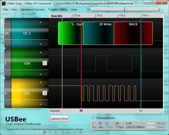
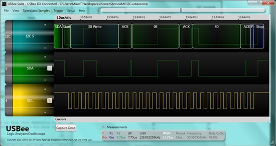
After this step is executed the SCL and SDA lines are both pulled low and remain low. This doesn't seem right to me. The code then goes into a loop attempting to send a byte of data out on SDA but gets stuck in a timeout loop waiting for ICSTR to become ready.

=================================================== 

// transmit data one byte at a time. 

for

(i = 0; i < in_length; i++)

{

i2c->ICDXR = src_buffer[i];


// wait for data to be copied to shift register.

cnt = 0;

do

{

if

(cnt++ > I2C_TIMEOUT)

{


// timed out waiting for data...reinit and return error.

I2C_init(i2c, g_clock_rate);

return

(ERR_TIMEOUT);

}

}


while

(!CHKBIT(i2c->ICSTR, ICXRDY));

==================================================

Data never shows up on the SDA line and there is no SCL. The SDA and SCL lines are connected to a AIC3204 and have 1K pullups on the SOM board.

Cany anyone give guidance on what may be happening?

(Also, I am obviously not cutting and pasting code properly from ccs4 into this forum window. Is there a "correct" way to do this that doesn't trash the format?)

Thx,

MikeH


  • After adjusting my logic analyzer sweep time, I discovered that there actually *is* data & clock on the lines. However, the screenshot below is triggered by the initilization of ICMDR during this step in the code

    MikeH said:

    // configure i2c for master transmit mode and release from reset.

    i2c->ICMDR = STT | MST | ICMDR_FREE | TRX | IRS;

    Here is the logic analyzer capture during the above step.

    After this step both SDA and SCL stay low for the duration of my capture buffer. The clock cycles are intermittently either 250ns or 500ns, not anywhere near 400khz.

    Any thoughts?

    Thx

    MikeH

  • MikeH said:

    // configure i2c for master transmit mode and release from reset.

    i2c->ICMDR = STT | MST | ICMDR_FREE | TRX | IRS;

    I have dissected the above line of code into separate bit setting instructions to try to isolate the problem. The modifed code is below.

    MikeH said:
      

    // configure i2c for master transmit mode and release from reset.  

    i2c->ICMDR = 0;

    i2c->ICMDR |= STT;

    i2c->ICMDR |= MST;

    i2c->ICMDR |= ICMDR_FREE;

    i2c->ICMDR |= TRX;

    i2c->ICMDR |= IRS;

    After single stepping through each instruction I find that the very last line (i2c->ICMDR |= IRS; ) is what triggers the data burst show in the screen capture.

    Again, any suggestions would be greatly appreciated.

    MikeH


  • The issue may be that the I2C module clock is running too fast. Did you enable the PLL before running the test, or are you running in bypass mode? If you are in bypass mode, I2C1 is running off Ref_CLK/4. Check the I2C1 Prescaler Register (ICPSC) and make sure the divider programmed will get you 400KHz.

    The reason you see the clock frequency changing is probably due to the sample rate of your scope not being fast enough.

    Jeff

  • Jeff,

    Thanks for the response.

    Yes, the PLL is initialzed as below:

    In my main.c initialization routine:

    I2C_init(I2C1, I2C_CLK_400K);


    ....which then calls (in evomapl138_i2c.c)

    // init I2C channel #1 

    // set global clock rate for future use.

    g_clock_rate = in_clock_rate; 

    // put i2c in reset.

    i2c->ICMDR = 0; 

    // configure clocks. 

    // set prescaler for ~8MHz interal i2c clock.

    i2c->ICPSC = 2;

    ...........


    case I2C_CLK_400K:

    i2c->ICCLKL = 5;

    i2c->ICCLKH = 5; 

    break;

    I believe the I2C clock is set properly......


  • That code assumes you are in PLL bypass mode with a 24MHz crystal:

    I2C1 is on SYSCLK4, so 24MHz/4 = 6MHz

    IPSC is 2, so 6MHz/3 = 2MHz

    ICCLKL and ICCLKH are 5, so 2MHz/5 = 400KHz

    If you have a GEL file loaded, it may be turning on the device PLL which means that SYSCLK4 will be much higher than 6MHz. Check the PLL0 configuration registers in to make sure it is in bypass mode for this test.

    Jeff

  • Jeff,

    Sounds reasonable. Heading out now but will check first thing in the AM.

    Thx,

    MikeH


  • BINGO Dude!! Check it out!

    Brilliant deduction. Thanks for your help!

    MikeH