This thread has been locked.

If you have a related question, please click the "Ask a related question" button in the top right corner. The newly created question will be automatically linked to this question.

TDA4VMXEVM: Booting J721E SoM with SD-Card MMC1 fails on my own Hardware

Part Number: TDA4VMXEVM


Booting J721E SoM with SD-Card MMC1 fails, if Hardware is not the TI Evalboard J721EXCP01EVM.


I have my own hardware to plug-in the TDA4 SoM (from the TI J7X Evalboard Kit)

The SD-Card reader is patched exactly the same as on the Evalboard (Schematic Sheet 23) to the SoM.

The SoM does NOT boot to this SD-Card and does not print any message to the console UART.


The same uSD Card connected to the Evalboard does boot and start-up as expected.


When I boot my own hardware to OSPI Flash, U-BOOT is starting and tries to boot from

SD-Card (MMC1), all files and configuration can be read from the SD-Card.

The only difference is the error-message "Card did not respond to voltage select!"

We are not able to find the reason for this message in the software.

Another difference is the transfer speed, my SD-Card is slower, because it is patched to

the TDA4 SoM module for testing purposes.

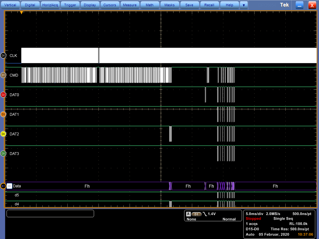
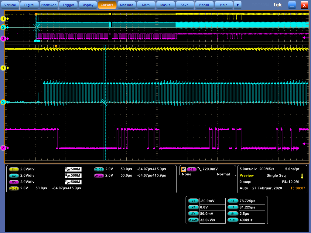
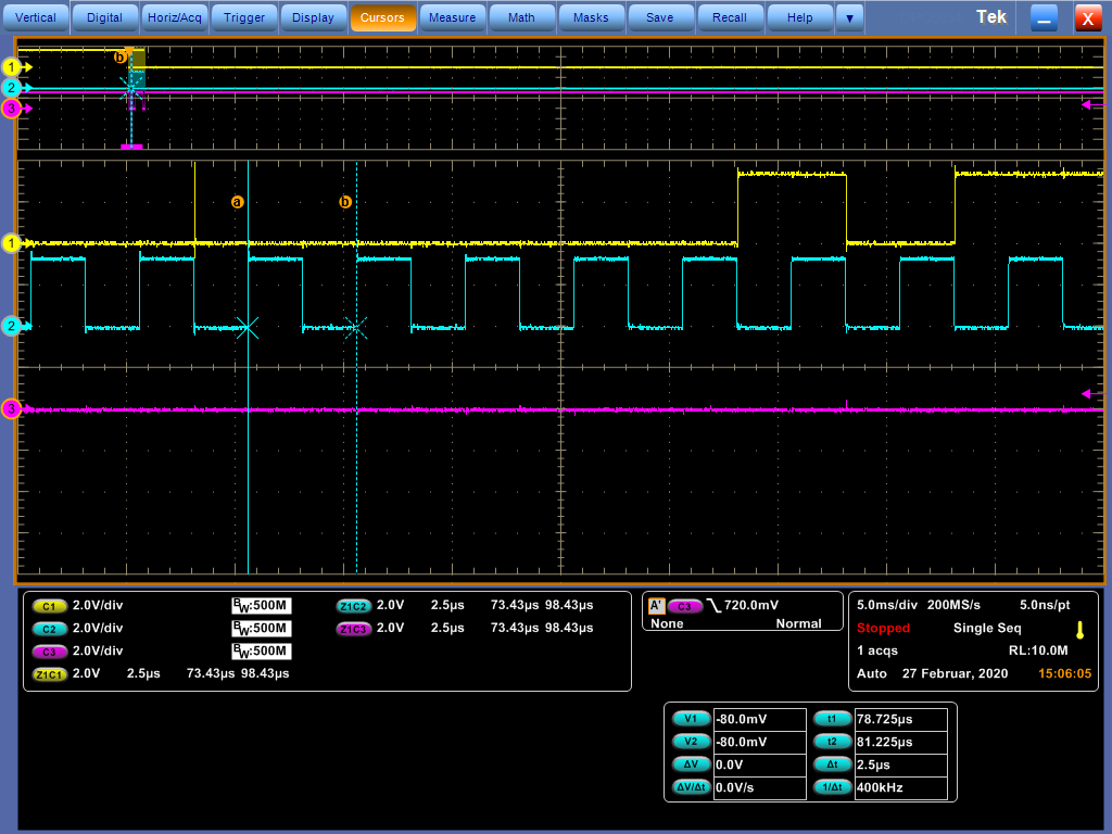
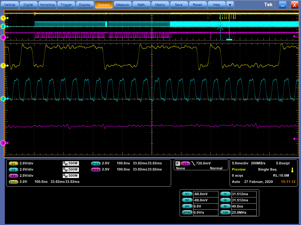
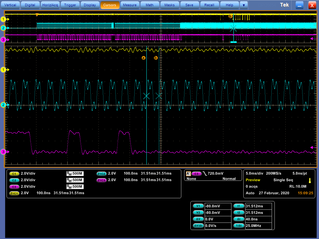
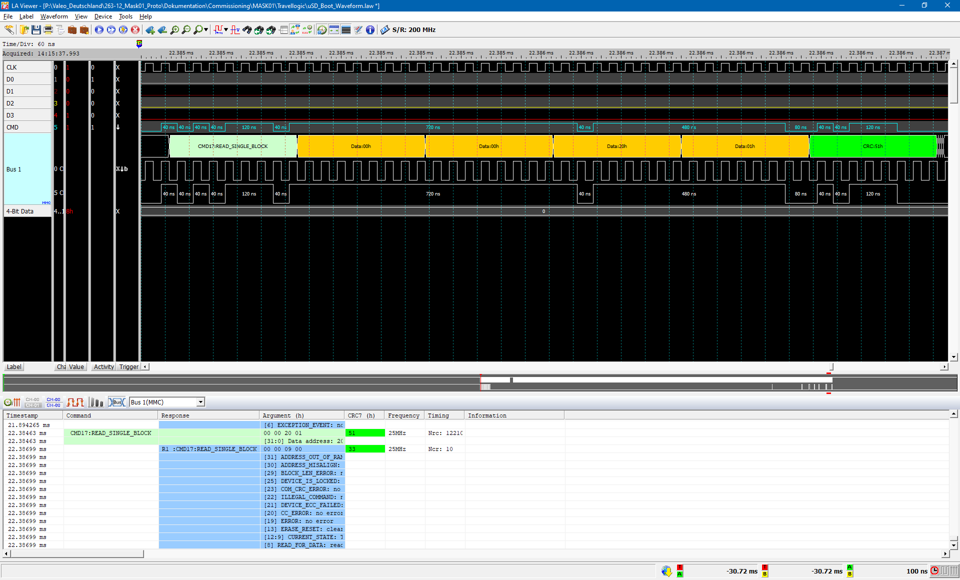
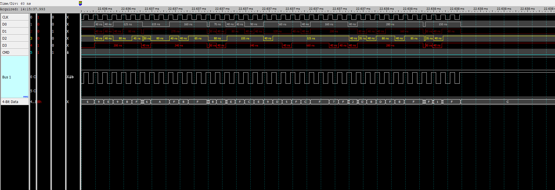
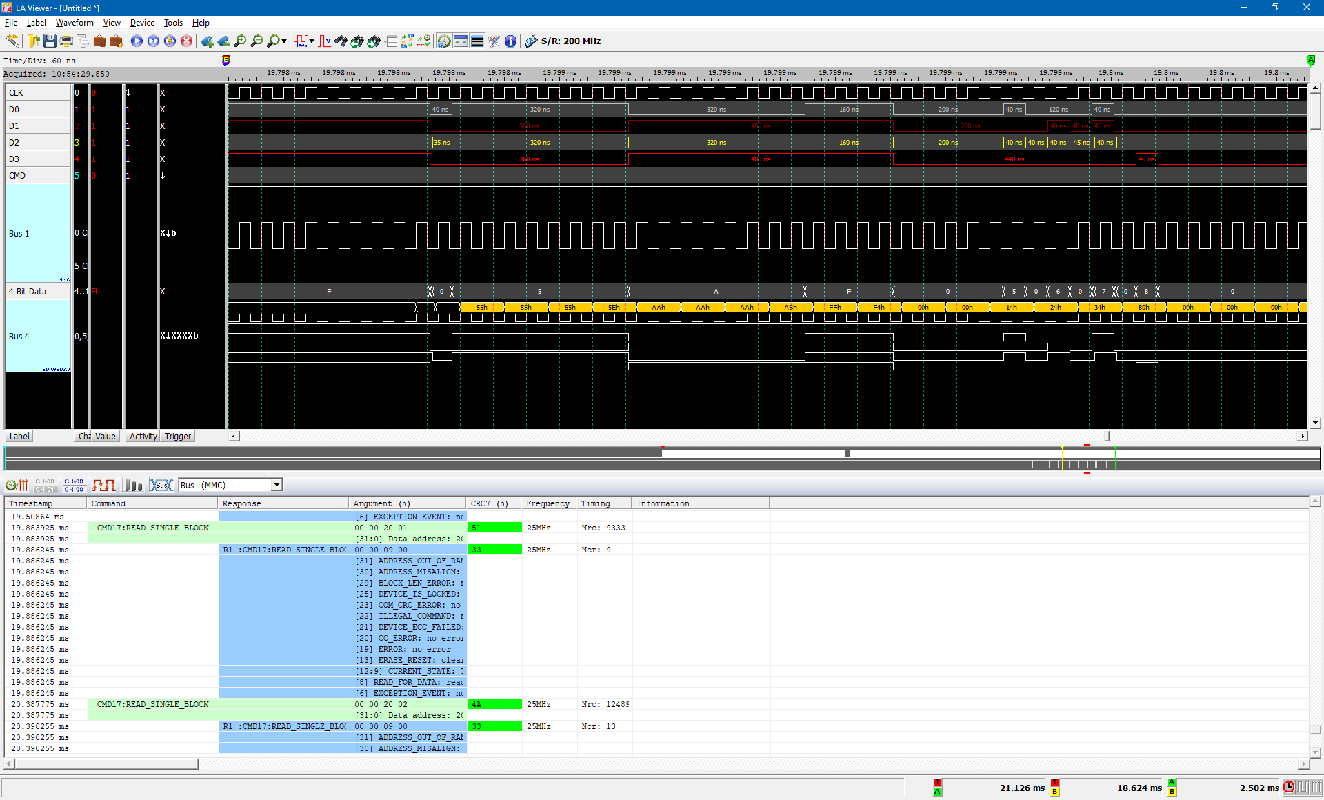
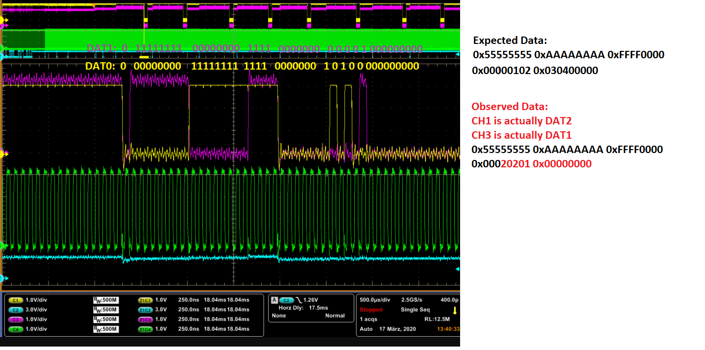
The Logic-Analyzer Traces show that the Bootloader is accessing the card and reading data in 4-bit mode.


Is there anything else beside the SD-Card, the SoM Bootloader ROM code requires to boot the SD-Card ?


<image is not copied>


SD-Card Boot from SoM, repeats several times, but SoM does not start


Log: EVM

*********************************************

U-Boot SPL 2019.01-g66126341c8 (Dec 11 2019 - 23:01:49 +0000)
SYSFW ABI: 2.6 (firmware rev 0x0013 '19.8.0-v2019.08-3-g8644f (Terri')
Trying to boot from MMC2
Loading Environment from MMC... *** Warning - No MMC card found, using default environment

Remoteproc 2 started successfully
** File not found /lib/firmware/j7-mcu-r5f0_0-fw **
Starting ATF on ARM64 core...

NOTICE:  BL31: v2.1(release):ti2019.02-rc4
NOTICE:  BL31: Built : 22:48:11, Dec 11 2019
I/TC:
I/TC: OP-TEE version: ti2019.02-89-ge5a8779-dev (gcc version 8.3.0 (GNU Toolchain for the A-profile Architecture 8.3-2019.03 (arm-rel-8.36))) #1 Wed Dec 11 22:59:07 UTC 2019 aarch64
I/TC: Initialized

U-Boot SPL 2019.01-g66126341c8 (Dec 11 2019 - 23:01:23 +0000)
Detected: J7X-BASE-CPB rev E3
Detected: J7X-VSC8514-ETH rev E2
Trying to boot from MMC2


U-Boot 2019.01-g66126341c8 (Dec 11 2019 - 23:01:23 +0000)

SoC:   J721E PG 1.0
Model: Texas Instruments K3 J721E SoC
Board: J721EX-PM2-SOM rev E7
DRAM:  4 GiB
Flash: 0 Bytes
MMC:   sdhci@4f80000: 0, sdhci@4fb0000: 1
Loading Environment from MMC... OK
In:    serial@2800000
Out:   serial@2800000
Err:   serial@2800000
Detected: J7X-BASE-CPB rev E3
Detected: J7X-VSC8514-ETH rev E2
Net:
Warning: ethernet@046000000 using MAC address from ROM
eth0: ethernet@046000000
Hit any key to stop autoboot:  0
switch to partitions #0, OK
mmc1 is current device
SD/MMC found on device 1
** Unable to read file boot.scr **
81 bytes read in 1 ms (79.1 KiB/s)
Loaded env from uEnv.txt
Importing environment from mmc1 ...
12364364 bytes read in 518 ms (22.8 MiB/s)
Load Remote Processor 3 with data@addr=0x80080000 12364364 bytes: Success!
** File not found /lib/firmware/j7-main-r5f1_0-fw **
9047884 bytes read in 377 ms (22.9 MiB/s)
Load Remote Processor 6 with data@addr=0x80080000 9047884 bytes: Success!
9046832 bytes read in 379 ms (22.8 MiB/s)
Load Remote Processor 7 with data@addr=0x80080000 9046832 bytes: Success!
11948304 bytes read in 499 ms (22.8 MiB/s)
Load Remote Processor 8 with data@addr=0x80080000 11948304 bytes: Success!
13338632 bytes read in 560 ms (22.7 MiB/s)
98400 bytes read in 5 ms (18.8 MiB/s)
3653 bytes read in 1 ms (3.5 MiB/s)
3742 bytes read in 2 ms (1.8 MiB/s)
## Flattened Device Tree blob at 82000000
   Booting using the fdt blob at 0x82000000
   Loading Device Tree to 00000000fdda6000, end 00000000fdec1fff ... OK

Log My own Hardware

***********************************************************

U-Boot SPL 2019.01-g66126341c8 (Dec 11 2019 - 23:01:49 +0000)
SYSFW ABI: 2.6 (firmware rev 0x0013 '19.8.0-v2019.08-3-g8644f (Terri')
Trying to boot from SPI
Loading Environment from MMC... spl: unsupported mmc boot device.
sdhci@4f80000 - probe failed: -19
spl: unsupported mmc boot device.
sdhci@4fb0000 - probe failed: -19
*** Warning - No MMC card found, using default environment

Loading rproc fw image from device 3 not supported!
Starting ATF on ARM64 core...

NOTICE:  BL31: v2.1(release):ti2019.02-rc4
NOTICE:  BL31: Built : 22:48:11, Dec 11 2019
I/TC:
I/TC: OP-TEE version: ti2019.02-89-ge5a8779-dev (gcc version 8.3.0 (GNU Toolchain for the A-profile Architecture 8.3-2019.03 (arm-rel-8.36))) #1 Wed Dec 11 22:59:07 UTC 2019 aarch64
I/TC: Initialized

U-Boot SPL 2019.01-g66126341c8 (Dec 11 2019 - 23:01:23 +0000)
Trying to boot from SPI


U-Boot 2019.01-g66126341c8 (Dec 11 2019 - 23:01:23 +0000)

SoC:   J721E PG 1.0
Model: Texas Instruments K3 J721E SoC
Board: J721EX-PM2-SOM rev E7
DRAM:  4 GiB
Flash: 0 Bytes
MMC:   sdhci@4f80000: 0, sdhci@4fb0000: 1
Loading Environment from MMC... Card did not respond to voltage select!
*** Warning - No block device, using default environment

In:    serial@2800000
Out:   serial@2800000
Err:   serial@2800000
Net:   Could not get PHY for ethernet@046000000: addr 0
phy_connect() failed
eth-1: ethernet@046000000
Hit any key to stop autoboot:  0
switch to partitions #0, OK
mmc1 is current device
SD/MMC found on device 1
** Unable to read file boot.scr **
81 bytes read in 2 ms (39.1 KiB/s)
Loaded env from uEnv.txt
Importing environment from mmc1 ...
Card did not respond to voltage select!
12364364 bytes read in 2003 ms (5.9 MiB/s)
Invalid seq: Enable primary core before loading secondary core
Load Remote Processor 3 with data@addr=0x80080000 12364364 bytes: Failed!
** File not found /lib/firmware/j7-main-r5f1_0-fw **
9047884 bytes read in 1463 ms (5.9 MiB/s)
Load Remote Processor 6 with data@addr=0x80080000 9047884 bytes: Success!
9046832 bytes read in 1465 ms (5.9 MiB/s)
Load Remote Processor 7 with data@addr=0x80080000 9046832 bytes: Success!
11948304 bytes read in 1933 ms (5.9 MiB/s)
Load Remote Processor 8 with data@addr=0x80080000 11948304 bytes: Success!
13338632 bytes read in 2161 ms (5.9 MiB/s)
98400 bytes read in 17 ms (5.5 MiB/s)
3653 bytes read in 1 ms (3.5 MiB/s)
3742 bytes read in 3 ms (1.2 MiB/s)
## Flattened Device Tree blob at 82000000
   Booting using the fdt blob at 0x82000000
   Loading Device Tree to 00000000fdda6000, end 00000000fdec1fff ... OK


  • Hi Daniel,

    According to your log, both instances of MMC failed to initialize

    sdhci@4f80000 - probe failed: -19
    spl: unsupported mmc boot device.
    sdhci@4fb0000 - probe failed: -19


    The log that you shared under "Log My own Hardware". What is the setup for this log?
    Is this log taken from OSPI boot mode?


    Regards,
    Vishal

  • Hi Vishal,

    When I have set Bootmode = MMC/SD, I do not have any logging output, I just can measure with the oscilloscope to see the ROM Bootloader accessing the SD-Card.

    To your question:

    Loading Environment from MMC... spl: unsupported mmc boot device.
    sdhci@4f80000 - probe failed: -19
    spl: unsupported mmc boot device.
    sdhci@4fb0000 - probe failed: -19
    *** Warning - No MMC card found, using default environment

    The boot switches are set to OSPI Boot here. This is the normal log output also on the Evalboard, if Boot switches are set to OSPI Boot.
    Here is the Log form the Eval Board:

    U-Boot SPL 2019.01-g66126341c8 (Dec 11 2019 - 23:01:49 +0000)
    SYSFW ABI: 2.6 (firmware rev 0x0013 '19.8.0-v2019.08-3-g8644f (Terri')
    Trying to boot from SPI
    Loading Environment from MMC... spl: unsupported mmc boot device.
    sdhci@4f80000 - probe failed: -19
    spl: unsupported mmc boot device.
    sdhci@4fb0000 - probe failed: -19
    *** Warning - No MMC card found, using default environment

    Loading rproc fw image from device 3 not supported!
    Loading rproc fw image from device 3 not supported!
    Starting ATF on ARM64 core...

    NOTICE:  BL31: v2.1(release):ti2019.02-rc4
    NOTICE:  BL31: Built : 22:48:11, Dec 11 2019
    I/TC:
    I/TC: OP-TEE version: ti2019.02-89-ge5a8779-dev (gcc version 8.3.0 (GNU Toolchain for the A-profile Architecture 8.3-2019.03 (arm-rel-8.36))) #1 Wed Dec 11 22:59:07 UTC 2019 aarch64
    I/TC: Initialized

    U-Boot SPL 2019.01-g66126341c8 (Dec 11 2019 - 23:01:23 +0000)
    Detected: J7X-BASE-CPB rev E3
    Detected: J7X-VSC8514-ETH rev E2
    Trying to boot from SPI


    U-Boot 2019.01-g66126341c8 (Dec 11 2019 - 23:01:23 +0000)

    SoC:   J721E PG 1.0
    Model: Texas Instruments K3 J721E SoC
    Board: J721EX-PM2-SOM rev E7
    DRAM:  4 GiB
    Flash: 0 Bytes
    MMC:   sdhci@4f80000: 0, sdhci@4fb0000: 1
    Loading Environment from MMC... OK
    In:    serial@2800000
    Out:   serial@2800000
    Err:   serial@2800000
    Detected: J7X-BASE-CPB rev E3
    Detected: J7X-VSC8514-ETH rev E2
    Net:
    Warning: ethernet@046000000 using MAC address from ROM
    eth0: ethernet@046000000
    Hit any key to stop autoboot:  0

  • Hi Vishal,

    we do have the latest SDK ?!

    Best Regards,

    Daniel

  • Hi Daniel,

    According to your logs you are not on latest release. Could you download the latest release from the link I shared?

    Try this patch in u-boot to see if the below u-boot patch helps
    https://git.ti.com/gitweb?p=ti-u-boot/ti-u-boot.git;a=commit;h=c83fb6e7a333292320617809e48499481c311aec

    Regards,
    Vishal

  • Hi Vishal,

    thank you for the link.

    My problem seems to be earlier in the Boot process. The ROM Bootloader seems not to be happy with

    the code read from the SD-Card, therefore I have no UART output and the processor will never reach the U-Boot code.

    Thanks and best regards,
    Daniel

  • Hi Daniel,

    Can you confirm that the tiboot3.bin file on SD card is the same as the one flashed to OSPI?

    Regards,
    Vishal

  • Hi Vishal,

    I have changed the tiboot3.bin file so it's now the same on the sd-card and in the OSPI Flash.

    There is no change regarding my problem with the sd-card boot, still no output to the console.

  • Hi Daniel,

    Does your board have JTAG capability? If yes, could you connect debugger and check where the R5 PC is located at?

    Regards,
    Vishal

  • Hi Vishal,

    The MCU_Cortex_R5_0 is suspended at address 0x4180040C

    Best Regards,

    Daniel

  • Hi Daniel,

    Could you also check what is the voltage supplied to MMC? 

    Regards,
    Vishal

  • Hi Vishal,

    yes, this is 3.3V (from VSYS_3V3)

    Best Regards,

    Daniel

  • Hi Daniel,

    The exact same SD card works on TI EVM?

    Regards,
    Vishal

  • Hi Vishal,

    yes ?! I can remove and move to the EVM and it boots...

    What is the "error-reason" you can see from the PC location of the R5 processor ?

    Best Regards,

    Daniel

  • It's not pointing to error. It's in idle state.

    We would like to compare the DEVSTAT registers between your board and TI EVM.

  • Hi Vishal,

    both registers (EVM and my HW) have same values:

    CTRLMMR_WKUP_DEVSTAT: 0x00000000

    CTRLMMR_MAIN_DEVSTAT: 0x00000041

    Best Regards,

    Daniel

  • Hi Vishal,

    I'm still waiting for an answer to my last reply.

    Have you found something ?

    Thanks and best regards,

    Daniel

  • Hi Daniel,

    Sorry for the delay. We are still looking in to this.

    Could you provide more details on below statement from your question?
    >> Another difference is the transfer speed, my SD-Card is slower, because it is patched tothe TDA4 SoM module for testing purposes.

    Regards,
    Vishal

  • Hi Vishal,

    we do not have a uSD card connector on our first PCB, so I have patched one to a small PCB and connected the signals and power with "Wire-Wrap wires", therefore the signal integrity is not so good as if we had the connector directly on the PCB...

    Best Regards,

    Daniel

  • Hi Daniel,

    Can you provide scope captures of the failed SD card access. We need to see CMD, DAT, and CLK lines.

    Regards,
    Vishal

  • Hi Vishal,

    The probe connections are coded into the file name (might be lost during upload). Ch.1 = DAT0, ch.2 = CLK, ch.3 = CMD

    The behaviour is different from boot to boot, here are some images from different tries

    Best Regards,

    Daniel

  • Hi Daniel,

    Would you be able to connect CCS and readout the MMC Status registers?
    Could you zoom in on the last CMD and DATA so we can make sure it is proper. Also, where are the signal lines probed?

    Regards,
    Vishal

  • Hi Vishal,

    The first command is this one

    the decoding is stopped after the following command / error ?

    Overview (at the blue cursor)

    detail:

    For this reason, I have added a 4-bit bus to see the data as good as even possible:

    2. last command:

    last command:

    last data (start):

    last data (end):

    I have tapped the analyzer at the uSD card side (J7 side is impossible to tap the probes)

    What register do you mean with "MMC Status Register" ?

    There are a lot of registers, but no one with this name, please specify exact name or address, thank you!

    Best Regards,

    Daniel

  • Daniel,

    Based on the log analyzer results, it appears the SD card stopped responding with data halfway through the last block and the SoC read the inactive high as "0xFF" data.

    A few questions...

    1. How are you letting the SD card know how many blocks to transfer?
    2. Can you share the same log capture when the SD card is read successfully on the EVM?
    3. Can you probe the signals so you can capture the waveform at time of failure?  Key Items to check:
    1. Was slew rate fast/slow?  This will indicate whether the SD card actively drove the signal to inactive stage
    2. How was signal integrity here?
    • This looks to be happening in bootloader.  Can you add debug prints for the following registers:
      1. MMCSD0_PRESENTSTATE (Offset 0x24)
      2. MMCSD0_NORMAL_INTR_STS (Offset 0x30)
      3. MMCSD0_ERROR_INTR_STS (Offset 0x32)

      Were you able to send a CMD13 after the failure to check on device status?

    Have a great day!

    Best Regards,

    Shiou Mei

  • Hello Shiou,

    we made a lot of tests and measurements today.

    The Evalboard works, reads block 0 and afterwards block 0x800 (see log)

    My own Hardware does not work, reads block 0, 1, 2, 3 and then block 0x200, 0x201.

    Data integrity seems to be good for block 0, but data is suspect.

    Afterwards, data integrity is no more good (see last block screenshot), and even data to clock relation has changed ! unexpected spikes in data detected

    Here are the images:

    read block 0: (ch.2 = CMD, ch.3 = DAT2, ch.4 = CLK)

    read last block (0x201)

    Log Decode for Own Hardware: (pdf)

    uSD_Boot_Report_OwnHW.pdf

    My own HW, Data:

    uSD_Boot_Data_OwnHW.pdf

    Evalkit Log:

    uSD_Boot_Evalkit.pdf

    If Logs are not readable (it seems so), please tell me how to upload a pdf / xlsx or similar file,

    Thank you and best regards,

    Daniel

  • Daniel,

    Can you confirm you have the same uboot and kernel images flashed onto the TI EVM as well as your hardware?  Moreover, what speed and voltage level did you intend for the MMC interface?

    Checking into the log, it appears CMD6 is faulty and it is currently switching the device for SDR50 operation.  Is this expected?  Please check your CMD6 argument against the SD Physical Layer Specification (simplified version available for download online) and update the value.  Bits [30:24] should be all 0x0s and Bits [23:16] should be all 0x0 or all 0xF and your log showed the DUT has these bits programmed to send out 0x7AAA.

    Have a great day!

    Best Regards,

    Shiou Mei

  • Adding a picture of the CMD6 structure for reference.

  • Daniel,

    Moreover, please confirm the following:

    1. Is the following screenshot the last waveform toggling on DAT line?  How repeatable is the spike in the image?

    2. Do you have pull up resistors on the DAT and CMD lines?  Since DAT line is pulled low, that means the device was still busy when it stopped sending out data.
      1. Another possibility is if you don't have PU resistors enabled and DAT0 was actually floating.  
    3. What SD card are you using?  Have you tried working with a different SD card?

    Have a great day!

    Best Regards,

    Shiou Mei

  • Hello Shiou,

    1. we have the same uboot and kernel image on both systems.

    My hardware is just a baseboard with sockets for the TDA4 SoM.

    2. I cannot modify any SD Card commands, because I just test the behaviour of the ROM Bootloader. What I do is the following:

    - I remove the uSD Card from the Evalboard Baseboard and insert this card into my patched uSD card reader connector

    - I configure the Boot-Mode on my own baseboard to "SD-Card Boot"

    - I turn ON power / press the POR Reset Button and measure, what the ROM Bootloader is doing

    - in UBOOT, the same card is readable WITHOUT ANY PROBLEMS

    3. Screenshots and spikes:

    - We have seen a lot of spikes in the second-last and last block read from the SD card.
    - Block 0 read (the first) seems to be fine AND THE TIMING DATA to CLOCK is COMPLETELY DIFFERENT
    - Data from Block 0 is garbage and after this, the Bootloader reads blocks 1,2,3, 0x200 and 0x201
    - at least at block 0x200 and block 0x201, THE DATA to CLOCK TIMING IS COMPLETELY DIFFERENT and
    we can recognize these spikes in data (repeatable, each time)

    (I think that reading block 0 and not receiving correct data is the source of the problem)

    block 0x00:

    block 0x200:

    different timing when reading block 0x201:

    - We have 47k pullup resistors on each DAT signal, CMD, CLK and Card-Detect
    - The rise time of the spike is much too fast for the 47k pullup, this signal must be driven actively by the card
    - We use the uSD Card from the TDA4 SoM shipping (SanDisk Edge 16GB HC A1), only with this type tested

    Best Regards,

    Daniel

  • Daniel,

    Please double check where you are probing block 00.  In your log it shows block 00 followed CMD17 immediately.  However, I don't see CMD line toggling right in front of the probe point in your capture.

    Can you also paste a screen capture of the first occurrence the timing changed on the buses?  Please also zoom in to the corresponding command right before that transfer.  Moreover, what data are you actually expecting to see in these blocks?  If you can change the blocks to all 0xAAAAAAAA or 0x55555555, it will be easier to isolate what caused the SD card to change timing.

    How many cards have you seen this behavior on & is it always reproducible?  Do you have another SD card you can use for testing?

    Have a great day!

    Best Regards,

    Shiou Mei

  • Hi Shiou,

    we have measured the commands and reading block0, images follow:

    1. Command 55:

    2. Command 06:

    3. command 17:

    Data from block 0:

    We could verify the data from block 0. Data and Checksum are sent correctly to the J7 !

    However, the J7 seems to detect an error and reads the block 1:

    which has all 0 data (timing is still o.k.)

    Timing seems to change at the first (unexpected) block 0x200 read

    - We could also verify the 4 data pins connection with switching the pins to GPIO and testing pullup/pulldown on the uSD Card side, the wiring is correct.

    - We also found that the U-BOOT is reading the SD card in 1-bit mode (because the device is not specified as 4-bit in the device tree)

    - We also tested a Verbatim Premium 32GB microSD card V10, but with this card we cannot see any data from block 0 at all, here is the screen-shot:

    and the log file:

    uSD_Card_Verbatim_Boot_fails.xlsx

    Best Regards,

    Daniel

  • Daniel,

    We are brainstorming internally to understand why the boot up failed on your setup.  In the interim, have you had a chance to modify the boot data so that is reads out 0x55555555, 0xAAAAAAAA, and 0xFFFF0000?  That will be easier for us to understand where the HS spike is coming from.  Moreover, were you able to achieve a working setup with Verbatim Premium 32GB microSD card V10 on the EVM?

    On another note, CMD6 previously mentioned was actually ACMD6, I missed the CMD55 in your initial report.  As a result the command structure is valid and won't cause the issues you are seeing.

    Have a great day!

    Best Regards,

    Shiou Mei

  • Hi Shiou,

    1. we did not made these measurements, because we could verify correct data from block #0, including boot signature and CRC.

    If this will help debugging, we can do the measurements next week.

    2. EVM is booting from the Verbatim uSD-Card.

    Best regards,

    Daniel

  • Hi Shiou,

    I did the measurements today.

    Oscilloscope channels:
    ch.1 DATA1
    ch.2 CMD
    ch.3 DATA2
    ch.4 CLK

    The ROM Bootloader reads block 0,1,2,3,0x2000, 0x2001, 0x2002, 0x2003.

    I have then prepared the data, the sd-card has following data (block 0)


    Block 0x2000 & 0x2001:

    The complete measurement (Excel)

    SD-Card_Test55AA_Log.xlsx

    The Block 0 read:

    and the oscilloscope (block 0)

    Block 0x2000:

    Oscilloscope block 0x2000:

    Read block 0x2001:

    oscilloscope block 0x2001:

    I could not see any spikes when reading blocks 2000 and up on several tries...

    Best Regards,

    Daniel

  • Daniel,

    Looks like your logic analyzer is not reading the correct data.  You may want to calibrate it.  On another note, the data coming back doesn't seem to be correct.  Am I missing something? 

  • Hi Shiou,

    I believe the data is correct. (The protocol analyzer decode is incorrect, because it is not decoding the start bit, but the oscilloscope shows correct data, I believe)
    Ch. 1 (yellow) is data bit 1
    Ch.3 (red) is data bit 3
    The bits are numered from 0 to 3, bit 0 is the right-most

    The expected data is NOT as you have written above, this data is only 4 bytes long and is set to 0x01020304 (not 00000102 and 03040000)

    The ch.1 (D1) is low for '5', is high for 'A', is high for 'F' and is high for the ID bytes '2' and '3'
    The ch. 3 (D2) is high for '5', is low for 'A', is high for 'F' and is high for ID byte '4'

    Best Regards,

    Daniel

  • Hi Daniel,

    Sorry for the delay, we are still discussing this behavior internally.

    Regards,
    Vishal

  • Daniel,

    In the interim, instead of just changing the first five words, can you modify the entire block 200 to a repeating pattern of 0xA5A5A5A5 and/or 0xF0F0F0F0.  The key is to stress the data lines so we can understand where the spike is coming from.

    You can keep Block 0 and Block 1 data the same since they didn't have any difference in behavior between working and non-working boot up.

    Have a great day!

    Thanks & Regards,

    Shiou Mei  

  • Hi Shiou,

    I cannot do any further measurements on my SD-Card patch, because the patch is mechanically broken and I cannot attach the measurement equipment anymore.

    We have the second revision of the board in production. This board has an SD-card reader directly on the PCB.

    I will do the measurements, once I have the new boards, but because of the corona-virus, the production is delayed.

    I come back to you, when I'm ready.

    Best Regards,

    Daniel

  • Daniel,

    Understand.  In the interim, can you confirm how you are setting up the SD card cage, and where you are probing the signals?  Schematics and picture will be beneficial.

    Take care.

    Thanks & Regards,

    Shiou Mei