This thread has been locked.

If you have a related question, please click the "Ask a related question" button in the top right corner. The newly created question will be automatically linked to this question.

AM5718: PRU clockout issue

Part Number: AM5718
Other Parts Discussed in Thread: AM5728, , AM5716

We want to output a 4 MHz clock on PR2_PRU0_CLOCKOUT. We have achieved this on an AM5728 in configuring the PRUSS_GPCFG0 register (see image below)

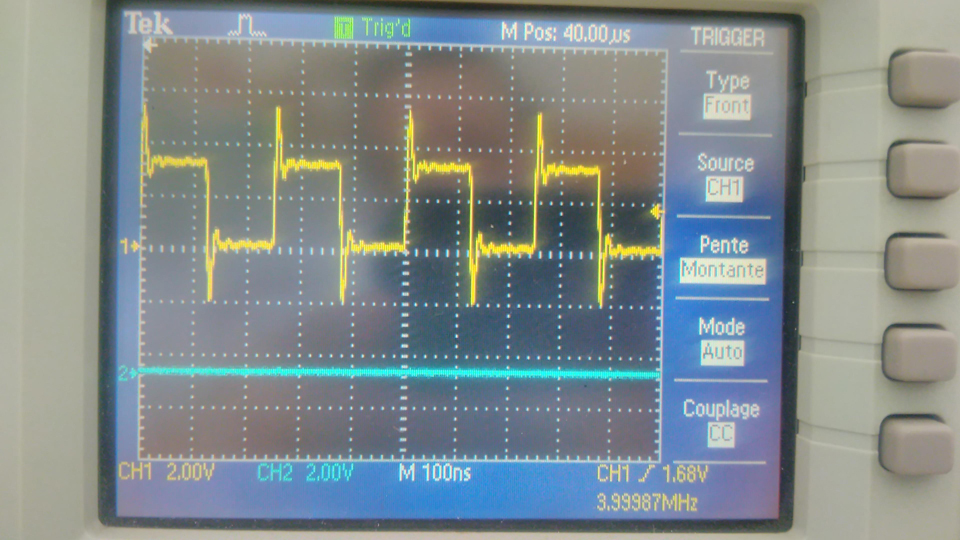
We have tried to do the same on an AM5718. However we got the following signal instead

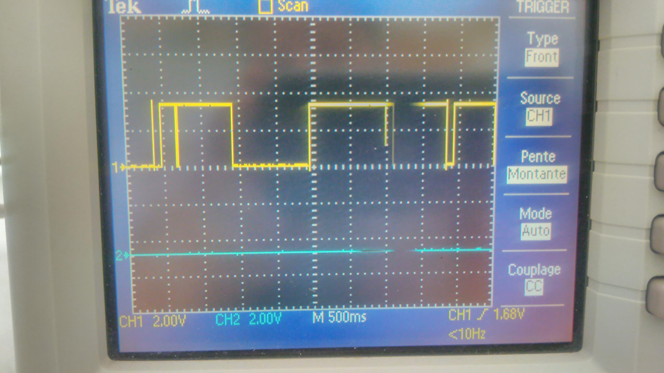
Is there something else to do in the case of the AM5718 ? Has anybody already used this output on the AM5718 ?

  • Hi,

    You should check that the pin functionality is not getting overwritten by other software.

  • Hi Biser,

    Thanks for your suggestion. I have checked the content of the relevant registers CTRL_CORE_PAD_GPIO6_11 and CFG_GPIO6_11_OEN from Linux running on the ARM15 with the correspondig commands : devmem2 0x4A003778 and devmem2 0x4844A0E8. I have got the same results on the AM5718 as on the AM5728: 0x0002000D and 0x00000000, respectively.

    Best regards,
    Gilbert

  • Hello Gilbert,

    Have you verified that your PRU firmware is initialized and running properly? Since you are using PRU GPO pin, I expect that the PRU is manually writing the pin low and high in a loop.

    Regards,

    Nick

  • Hello Nick,

    Thank you for willing to help me. I don't think so. According to figure 30-14 (reproduced here below) of the AM5718 Technical Reference Manual,

    the output clock should be generated without setting the pin up and down by a software running on the PRU.

    Best regards,

    Gilbert

  • Hello Gilbert,

    I stand corrected, you are right. Could you confirm your PRUSS_GPCFG0 settings?

    Is there anything else connected to the trace you are measuring that could be affecting results? e.g., another pin of the chip, etc?

    Regards,

    Nick

  • Hello Nick,

    Thank you for giving me new hints to solve the problem.

    This is the hexadecimal value of the PRUSS_GPCFG0 register as returned by devmem2 :
    0x0C6BC000
    and the decoding I have made:

    00|00 11|0|0 0110| 1011 1|1|0|0 0000| 0000 0|0|00
    31:30 RESERVED            0x0
    29:26 PR1_PRU0_GP_MUX_SEL 0011: SD mode
    25    PRU0_GPO_SH_SEL     0x0 = gpo_sh0 is selected
    24:20 PRU0_GPO_DIV1       0x06 = div 4.0
    19:15 PRU0_GPO_DIV0       0x17 = div 12.5
    14    PRU0_GPO_MODE       0x1 = Serial output mode
    13    PRU0_GPI_SB Start Bit event for 28-bit shift mode.
    12:8  PRU0_GPI_DIV1       0x00 = div 1.0
    7:3   PRU0_GPI_DIV0       0x00 = div 1.0
    2     PRU0_GPI_CLK_MODE Parallel 16-bit capture mode clock edge.
    1:0   PRU0_GPI_MODE       0x0 = Direct input mode

    The field values are the ones they should be in my opinion.

    According to the board schematics, there are no other components connected to the processor pin.

    The pin is configured as i2c3_scl by the Linux OS running on the ARM15, but we reprogram it
    as pr2_pru0_gpo1. The devmem2 output value confirms that the reprogramming has been successful.

    Any other suggestions ?

    Best regards,
    Gilbert


  • Hi Gilbert,

    you should also check that Bit 31 of R30 is constantly 1.

    With it the Shift Out mode can be started and stopped.

    You could also check, whether the Pin is routed to the PRU at all by setting GPO_Mode to 0 and manually toggling the pin in a PRU software loop as a test.  This could help to narrow down the problem.

    Best regards,

    Sebastian (just another TI customer)

  • Hi Sebastian,

    Thank you for your suggestions.

    I have first tried to set bit 31 of R30 after having set GPO_Mode to 1, but the signal behaviour remained the same.

    Secondly, I tested the toggling of the pin with GPO_Mode set to 0. The expected square wave is visible on the
    oscilloscope trace but only for a certain time. I noticed that the same occurs with the clockout in serial output mode.
    The pin output seems to be the multiplexing of the expected signal with another slower varying signal. This
    cannot be due to a change in pinmux configuration, since our software change the pinmux only once...

    Finally, I also tried to change the processor in case it was damaged. Since I had no other AM5718 at hand, I tried
    with an AM5716 and got the same result.

    Unfortunately, I am still not understanding what is happening...

    Best regards,
    Gilbert

  • Hello Gilbert,

    1) Why are you using Sigma delta mode? I would expect you to use GPIO mode

    2) When you say "we reprogram the pinmuxing", you are reprogramming it from Linux right? PRU should not have permissions to write to the config registers that control pinmuxing.

    Regards,

    Nick

  • Hello Nick,

    Thank you for the time spent in trying to support us.

    Concerning your questions:

    1) According to AM5718 TRM page 7265, " The pr<k>_pru0_gpo1 signal (muxed with SD0_D) can be used as SD_CLKOUT" to generate clock for the Sigma-Delta peripheral, e.g. microphone. This is our goal. However, we tried with the GPIO mode and got the same result.

    2) We have reprogrammed the pinmuxing with a software running on DSP1, because we use this platform for signal processing. However, we are on the way to generate a new configuration file to be included in the u-boot.

    Best regards,

    Gilbert

  • Dear all,

    I could remove this behaviour in setting PRUSS_SYSCFG bits 3:2 STANDBY_MODE
    from reset value 0x2 = Smart standby mode: Standby requested by initiator depending on internal conditions
    to 0x1 = No standby mode: Initiator unconditionally out of standby

    Thanks again for your willing to help.

    Best regards,
    Gilbert

  • Hello Gilbert,

    Glad you were able to figure it out, and thanks for posting your solution! I have not played around with STANDBY_MODE myself, interesting that it affects the clockout signal.

    Regards,

    Nick