This thread has been locked.

If you have a related question, please click the "Ask a related question" button in the top right corner. The newly created question will be automatically linked to this question.

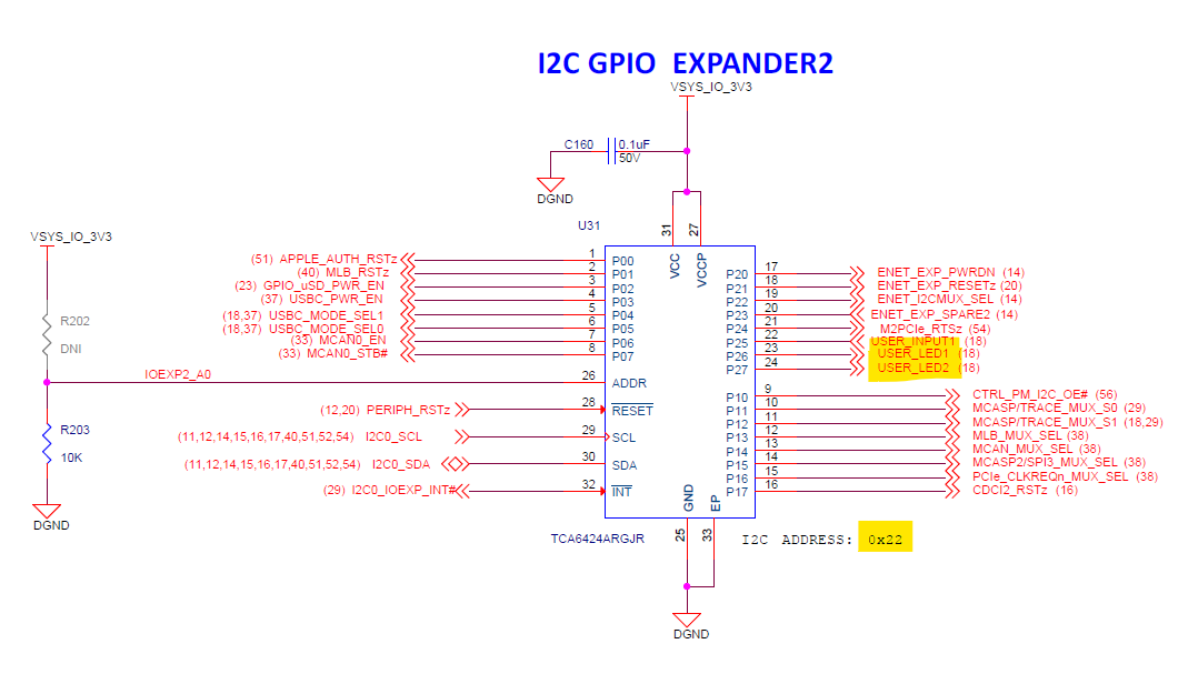
TDA4VMXEVM: USER_LED1 & USER_LED2 through I2C GPIO EXPANDER2 (TCA6424ARGJR)

Part Number: TDA4VMXEVM

Hello,

I am using TDA4 EVM. In the Common Processor Board, there are 2 User LEDs. 

The confusing part is I2C0 which is controlling this expansion board is also connected to other ICs. 

Kindly guide me how to toggle the LEDs ?

Thanks & Regards,

Gurudath

  • Hi,

    The i2c expander which controls the USER LEDs is at the bus i2c0 and chip address 0x21

    This can be done using i2cset command

    The LEDs are connected to the pins P26 and P27

    Regards,

    NIkhil D

  • Hello Naveen,

    Thanks for the response. In the I2C command explanation, I found the below warning. So could you please give the i2cset command format for USER_LED1? :

    WARNING

    i2cset can be extremely dangerous if used improperly. It can confuse your I2C bus, cause data loss, or have more serious side effects. Writing to a serial EEPROM on a memory DIMM (chip addresses between 0x50 and 0x57) may DESTROY your memory, leaving your system unbootable! Be extremely careful using this program.

    Thank you.

  • Please check the help and manuals for i2cset

    e.g. i2cset --help or i2cset -h should give you that.

    Typically it is like following:

    i2cset -f -y <bus num> <chip address> <reg address> <value>

    You need to figure out the address and values for the chip you are writing to.

    Refer to TRM, find out the datasheet of the GPIO expander for details of the registers.

    Regards,

    Nikhil D

  • Hi Nikhil,

    I tried the following command to switch ON the LED1 at P26:

    i2cset -y 0 0x21 0x06 0xBF 

    But I got "Write Failed" as the response.

    Then I tried to change the configuration of P26 to Output with the following command:

    i2cset -y 0 0x21 0x0E 0xBF 

    Then also i got  "Write Failed" as the response.

    I am trying to read the i2c register value with the following command:

    i2cget -y 0x21 0x06

    I am getting "read failed" as response.

    So i2c is not working. What could be the reason and how can I debug this?

  • You forgot the -f argument

    Regards,

    Nikhil D

  • Even with the -f argument, I am getting same result.

    What could be the reason and how can I debug this?

    if i execute "i2cdetect -l" the i2c0 is listed.

  • Even with the -f argument, I am getting same result.

    What could be the reason and how can I debug this?

    if i execute "i2cdetect -l" the i2c0 is listed. Below is the output, where the 0x21 is not listed :

    i2cdetect -y 0
    Warning: Can't use SMBus Quick Write command, will skip some addresses
         0  1  2  3  4  5  6  7  8  9  a  b  c  d  e  f
    00:                                                
    10:                                                
    20:                                                
    30: -- -- -- -- -- -- -- --                        
    40:                                                
    50: 50 51 -- -- -- -- -- -- -- -- -- -- -- -- -- --
    60:                                                
    70: 

  • Try i2cdetect -r -y 0

    Ideally, i2cdetect should first show the device responding with adrress acks.

    Your device needs to be shown first. That confirms the address is correct.

    Regards,

    Nikhil D

  • Even with this it is giving the same result.

    i2cget, i2cset are failed.

    Is it possible to have a call for further clarification? This may speedup the solution. Request your opinion.

    Thanks & Regards,

    Gurudath

  • Hi Gurudath,

    Try "i2cdetect -r -y 3"
    This is main_i2c0, there are other mcu/main i2c that gets number 0, 1 and 2. So main i2c numbering starts from 3.

    Also the GPIO expander is on Address 0x22. Snippet from EVM common processor board schematics shown below.


    Below commands worked on EVM to toggle LED,

    i2cdetect -r -y 3
    i2cset -f -y 3 0x22 0x06 0xBF
    i2cset -f -y 3 0x22 0x0E 0xBF


    Regards,
    Vishal

  • I tried the recommended commands. I am not getting Read/Write Failed status now. However the LED is not blinking.

    So I have 2 questions:

    1. As mentioned in the same schematic document, the table shows address of the device as 0x21. Which one is correct?

    2. As I mentioned in the other post, 

    How can we include the slave address mentioned in the datasheet? 

    It is ok for me to write a C function if the commands are not yet prepared for this ASIC. So please guide me further.

  • It seems there is a mistake in the schematics.

    You can check the correct address of the LED when you run

    i2cdetect -r -y 3 #This will show up a device at 0x22

    GPIO expander datasheet http://www.ti.com/lit/ds/symlink/tca6424a.pdf

    You can run following to see that it has the same register map as of the part TCA6424ARGJR

    i2cdump -f -y 3 0x22

    You can set the direction of the P26 and P27 to output by setting the bits to 0

    val=`i2cget -f -y 3 0x22 0x0e`

    echo $val

    val=`printf 0x%x $(( $val & 0x3f))`  #Mask the 6th and 7th bit to set them to zero

    echo $val

    i2cset -f -y 3 0x22 0x0e $val

    Similary set the output value to high

    val=`i2cget -f -y 3 0x22 0x06`

    echo $val

    val=`printf 0x%x $(( $val & 0x3f))`  #Mask the 6th and 7th bit to set them to zero

    echo $val

    i2cset -f -y 3 0x22 0x06 $val

    I hope you find this helpful.

    Regards,

    Nikhil D

  • Hi Nikhil,

    This resolved my issue. To summarize, there were 2 mistakes in the earlier try

    1. i2c Device address was 0x21 as mentioned in a table of the schematics.
    2.  i2c bus number was used as 0 as the i2c0 is mentioned in schematics. There is no additional information that this is mapped to 3 in the actual i2c bus list.

    Request you to note the correction of this information in the next release of schematics.

    Thanks you very much for your support.

  • Hi,

    Yes, schematics table will be updated to reflect correct address.
    Closing this thread.

    Regards,
    Vishal