This thread has been locked.

If you have a related question, please click the "Ask a related question" button in the top right corner. The newly created question will be automatically linked to this question.

AM6526: MMCSD and Silicon Revision 2.0 Question

Part Number: AM6526

First some quick back info...

AM65x/DRA80xM Silicon Revision 1.0:

  • MMC0_SDCD == VDDSHV6
  • MMC0_SDWP == VDDSHV6
  • MMC1_SDCD == VDDSHV7
  • MMC1_SDWP == VDDSHV7

To free up VDDSHV6 and VDDSHV7 for "dynamic voltage change"....Silicon Revision 2.0:

  • MMC0_SDCD == VDDS_OSC1
  • MMC0_SDWP == VDDS_OSC1
  • MMC1_SDCD == VDDS_OSC1
  • MMC1_SDWP == VDDS_OSC1

Question:

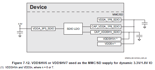
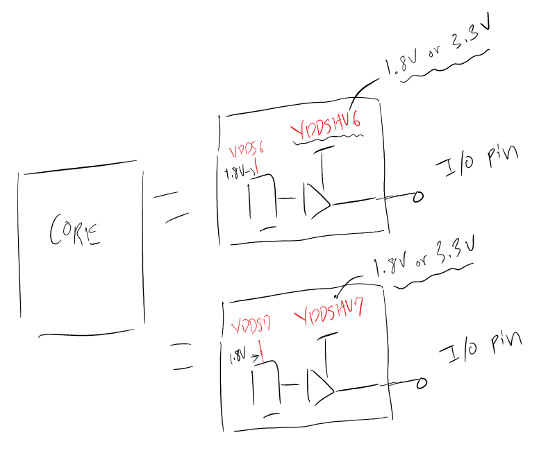
  1. "Dynamic voltage change" capability refers to the ability to use both 1.8V LVS SD Cards, and 3.3V SD Cards, yes?
  2. Is it possible to have 1 of the MMCSD (MMC0...) set to 1.8V, while the other (MMC1...) is set to communicates at 3.3V?

It seems since MMC0... used VDDSHV6, and MMC1... used VDDSHV7, they should be able to work simultaneously with different voltage SD cards...(1 card at 1.8V, the other at 3.3V)

Can you confirm this?

Regards,

Darren

  • Hi Darren,

    1) w.r.t SD cards dynamic voltage change referes to switch from 3.3V to 1.8V. You are correct.
    2) Since the voltage rails are separate they are independent and can stay at different voltage levels.

    Thanks,
    Keerthy

  • Hi Keerthy,

    I have a follow question regarding the actual implementation.

    Let us assume there are two SD CARD connectors on a board, CN1 and CN2, and both have an SD CARD inserted.

    CN1 is connected to the AM6526 via MMCSD0.
    CN2 is connected to the AM6526 via MMCSD1.

    How do you configure VDDSn or VDDSHVn so that:

    • 1st SD CARD @ 1.8V or 3.3V, independent from...⇓
    • 2nd SD CARD @ 3.3V or 1.8V

    Are the connections for VDDSHV & VDDS the same as shown in the older DS? (see below image)

    • (Rev.H、JAJSGC3H –NOVEMBER 2017–REVISED JUNE 2019)

    If connections are made following the diagram as shown in Figure 7-12, there is only one "CAP_VDDSHV_SDIO" pin to connect VDDSHVn to...so if VDDSHV6 was connected here, then VDDSHV7 can't be...

    Honestly, this is a little beyond me. If you can summarize the proper connection for two SD CARDS for dynamic 3.3V/1.8V functionality, independent of each other, it would be a huge help.

    Regards,

    Darren

  • Darren,

    This is a board design related question. Could you please raise a separate query
    with the above details so that right owner could be assigned.

    Thanks,
    Keerthy

  • Hi Keerthy,

    Before raising a new post let me try asking this...

    There is documentation for migrating from Silicon Revision 1.0 to SR 2.0, but no DS for SR 2.0 yet.

    The last DS to have a discussion/example of the configuration for dynamic voltage with MMCSD is Figure 7-12 from the Revision H datasheet.

    The datasheet gives an example for dynamic voltage by connecting VDDSHVn (6 or 7?) to CAP_VDDSHV_SDIO.

    But there is only 1 CAP_VDDSHV_SDIO on the AM5x device...if so, then how can, for example, 1 VDDSHVn be dynamically set to 1.8V, while the other VDDSHVn is set dynamically for 3.3V?

    Am I misunderstanding something in relation to the VDDSHVn functionality?

    Regards,

    Darren

  • Hi Keerthy,

    Let me start over and try go through this step-by-step...

    • My understanding (as shown in the below image) is that the SDIO_LDO can be used to set the VDDSHVn to 3.3V or 1.8V.

    • This VDDSHVn is the power supply for the IO module (while VDDSn is the supply for the IO logic, usually 1.8V)
      1. See below image
    • Is it possible to change the voltage of VDDSHVn by changing the SDIO_LDO for 3.3V or 1.8V, without having to reset the entire device?
      • I ask because the SR 1.0 Erratta discusses the need for PORz when changing this voltage...

  • Darren,

    I believe you have created a new thread & is assigned to the relevant expert.
    I am closing this one.

    Thanks,
    Keerthy