This thread has been locked.

If you have a related question, please click the "Ask a related question" button in the top right corner. The newly created question will be automatically linked to this question.

AM3358: DCAN configuration

Part Number: AM3358

Hi. TI.

I would like to add a DCAN device to the EVMSK device.

So I did the following:

The software versions I currently use are:
ti-processor-sdk-linux-am335x-evm-06.01.00.08

========================================================================

1. Connect CAN Transceiver to EVMSK.

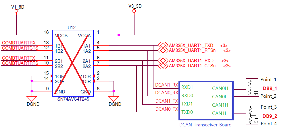
AM335x Starter Kit (SK) Refer to the Schematic.pdf document and connect two CAN Transceivers to the following circuit.

2. Device tree modification.

/ti-processor-sdk-linux-am335x-evm-06.01.00.08/board-support/linux-4.19.59+gitAUTOINC+5f8c1c6121-g5f8c1c6121/arch/arm/boot/dts/am335x-evmsk.dts


&am33xx_pinmux {


           dcan0_pins_default: dcan0_pins_default {

                     pinctrl-single,pins = <

                                AM33XX_IOPAD(0x978, PIN_INPUT | MUX_MODE0)             /* uart1_ctsn.d_can0_tx */

                                AM33XX_IOPAD(0x97C, PIN_OUTPUT_PULLDOWN | MUX_MODE0) /* uart1_rtsn.d_can0_rx */

                     >;

           };

           dcan1_pins_default: dcan1_pins_default {

                     pinctrl-single,pins = <

                                AM33XX_IOPAD(0x984, PIN_OUTPUT_PULLDOWN | MUX_MODE0) /* uart1_tx.d_can1_rx */

                                AM33XX_IOPAD(0x980, PIN_INPUT_PULLUP | MUX_MODE0)     /* uart1_rx.d_can1_tx*/

                     >;

           };

}

&dcan0 {

           status = "okay";

           pinctrl-names = "default";

           pinctrl-0 = <&dcan0_pins_default>;

};

&dcan1 {

           status = "okay";

           pinctrl-names = "default";

           pinctrl-0 = <&dcan1_pins_default>;

};

3. Build and SD Card Flash

========================================================================

I have a question.

Q1. Did I write the dts file correctly?

Q2. Is there anything else I need to do to activate CAN?

Q3. How to check if CAN is enabled?
      What devices appear in /dev/ ?

Thank you in advance.


Regards,
Simon

  • Hi,

    What you are trying to enable is not supported on the EVM-SK platform by TI since this requires board modifications. The UART1 that you are using to attach to a CAN device is in use with the wifi module on the board for bluetooth support. To connect to a CAN device there will require a line termination circuit to make sure the electrical signals are correct and balanced. You might consider using the expansion headers on a Beagle Bone Black to see if this might meet your needs, again you will need to bread board a line termination circuit.

    The other issue would be the pin mux entries in the DTS file has the incorrect modes for the DCAN interface, these need to be mode 2 for both, not 0.

    Best Regards,

    Schuyler

  • Dear. Schuyler


    Thank you for your answer.


    I am trying to configure a board that supports Gigabit Ethernet switch and two DCANs at the same time.

    I received an answer from TI that there is no product supporting both at the same time.

    So, I want to add DCAN function to EVMSK.
    I want to connect CAN Tranceiver to UART1 because BT and WIFI are not required.


    1. As you have informed, the dts file has been modified as follows.
    &dcan0 {
        status = "okay";
        pinctrl-names = "default";
        pinctrl-2 = <&dcan0_pins_default>;
    };
    &dcan1 {
        status = "okay";
        pinctrl-names = "default";
        pinctrl-2 = <&dcan1_pins_default>;
    };

    2. The hardware has been modified as follows.
    2-1. U12 IC removed.
    2-2. The CAN Transceiver Board with line termination circuit is connected as shown below.

    3. Build and SD Card Flash

    4. ifconfig -a
    root@am335x-evm:~# ifconfig -a
    can0 Link encap:UNSPEC HWaddr 00-00-00-00-00-00-00-00-00-00-00-00-00-00-00-00
        NOARP MTU:16 Metric:1
        RX packets:0 errors:0 dropped:0 overruns:0 frame:0
        TX packets:0 errors:0 dropped:0 overruns:0 carrier:0
        collisions:0 txqueuelen:10
        RX bytes:0 (0.0 B) TX bytes:0 (0.0 B)
        Interrupt:36

    can1 Link encap:UNSPEC HWaddr 00-00-00-00-00-00-00-00-00-00-00-00-00-00-00-00
        NOARP MTU:16 Metric:1
        RX packets:0 errors:0 dropped:0 overruns:0 frame:0
        TX packets:0 errors:0 dropped:0 overruns:0 carrier:0
        collisions:0 txqueuelen:10
        RX bytes:0 (0.0 B) TX bytes:0 (0.0 B)
        Interrupt:37

    5. loopback test
    5.1 Initialize CAN Bus (loopback)
    root@am335x-evm:~# ip link set can0 type can bitrate 500000 loopback on
    5.2 Start CAN Bus
    root@am335x-evm:~# ip link set can0 up
    5.3 cansend ( Another terminal )
    root@am335x-evm:~# cansend can0 001#DEADBEEF
    5.4 candump
    root@am335x-evm:~# candump can0
      can0  001  [4]  DE AD BE EF
      can0  001  [4]  DE AD BE EF


    Q1. Is there anything else I need to do to activate CAN?

    Q2. How to check if CAN is activated normally?
        Is it possible to check with loopback test?

    Q3. When checking the received message with candump during loopback test, a duplicate message is received.
        Is this normal?


    Regards,
    Simon

  • Hi,

    I think I need to apologize as I may not have explained what mux_mode2 is for the CAN1 entry. It should be something like this for the RX and TX pins in the dcan1_pins_default structure:

    AM33XX_IOPAD(0x984, PIN_OUTPUT_PULLDOWN | MUX_MODE2) /* uart1_tx.d_can1_rx */

    AM33XX_IOPAD(0x980, PIN_INPUT_PULLUP | MUX_MODE2)     /* uart1_rx.d_can1_tx*/

    You should be able to loopback if you choose. But the pin mux needs to be correct.

    Best Regards,

    Schuyler

  • Dear. Schuyler


    I applied the following information you gave me.

    &am33xx_pinmux {
      dcan0_pins_default: dcan0_pins_default {
        pinctrl-single,pins = <
        AM33XX_IOPAD(0x978, PIN_INPUT | MUX_MODE0) /* uart1_ctsn.d_can0_tx */
        AM33XX_IOPAD(0x97C, PIN_OUTPUT_PULLDOWN | MUX_MODE0) /* uart1_rtsn.d_can0_rx */
        >;
      };
      dcan1_pins_default: dcan1_pins_default {
        pinctrl-single,pins = <
        AM33XX_IOPAD(0x984, PIN_OUTPUT_PULLDOWN | MUX_MODE2) /* uart1_tx.d_can1_rx */
        AM33XX_IOPAD(0x980, PIN_INPUT_PULLUP | MUX_MODE2) /* uart1_rx.d_can1_tx*/
        >;
      };
    }

    &dcan0 {
      status = "okay";
      pinctrl-names = "default";
      pinctrl-2 = <&dcan0_pins_default>;
    };
    &dcan1 {
      status = "okay";
      pinctrl-names = "default";
      pinctrl-2 = <&dcan1_pins_default>;
    };

    However, there are still duplicate messages when loopback test.
    Is there anything else I need to check?

    root@am335x-evm:~# ip link set can0 type can bitrate 500000 loopback on
    root@am335x-evm:~# ip link set can0 up
    root@am335x-evm:~# candump can0
    can0 001 [4] DE AD BE EF
    can0 001 [4] DE AD BE EF

    root@am335x-evm:~# ip link set can1 type can bitrate 500000 loopback on
    root@am335x-evm:~# ip link set can1 up
    root@am335x-evm:~# candump can1
    can1 002 [4] DE AD BE EF
    can1 002 [4] DE AD BE EF

    However, there are still duplicate messages when loopback test.
    Is there anything else I need to check?


    Regards,
    Simon

  • Hi,

    To confirm, you are connecting can0 to can1 with wires? If so have you tried it without the loopback option being set on the ip command? Could you also show the cansend line and the candump line together? Is the cansend the same as in first post?  

    Please post the results of these lines as well.

    ip link show can1   

    cat /proc/net/can/stats

    Best Regards,

    Schuyler 

  • Dear. Schuyler


    Please check the following answers to your questions.

    A1. The actual test circuit configuration is connected as follows.

        can0 and can1 are not wired together.


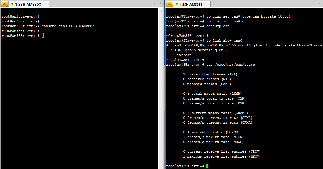
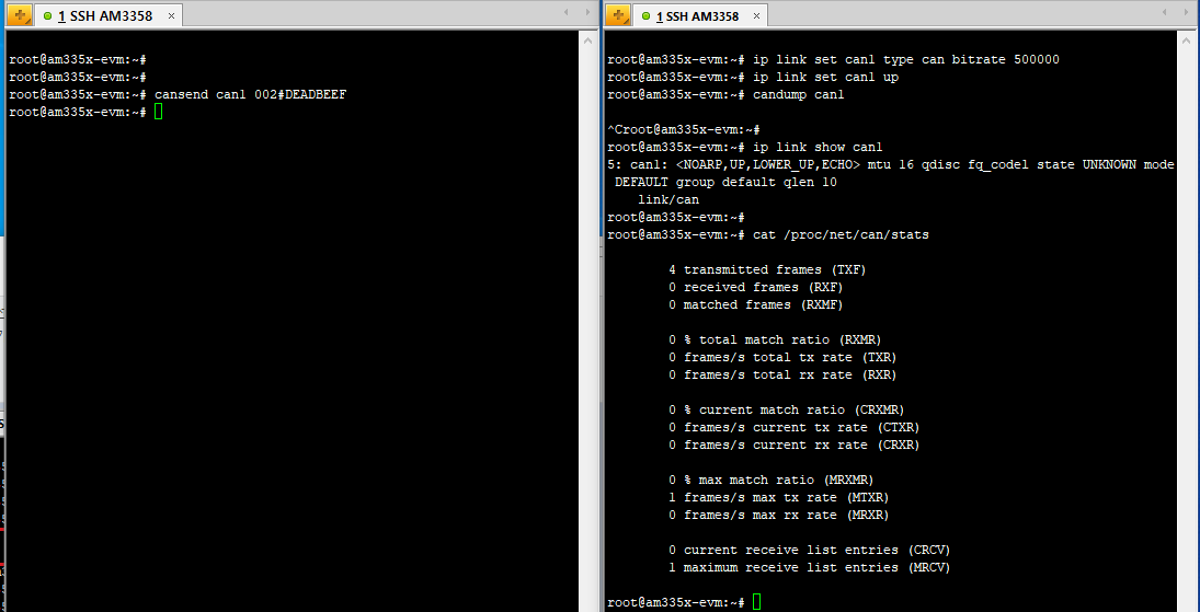
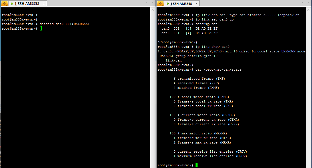
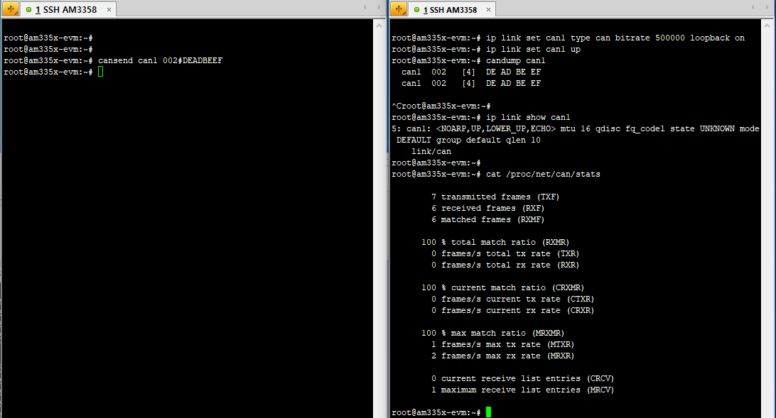
    A2. Here is the result of retesting:
      If I test it without loopback, there is no response from candump.

      1. can0 no loopback test


    2. can1 no loopback test


    3. can0 loopback test


    4. can1 loopback test

    Regards,
    Simon

  • Hi, 

    I apologize for the delay. Could you run the following command ip command with these options, the state of the bus needs to be looked at.

    ip -d -s link show can0

    What is needed is a scope to show the data transmitted the bus. Do you have a scope that could be to look at the traffic on the CANBUS?

    You mentioned that can0 and can1 are connected to each other is this correct still? In the non loopback mode when the stats are being read there is not any RX frames on the can0 interface. Where are the expected frames coming from?

    I am going to close the other thread that you started and continue to use this thread. Again apologies for the delay.

    Best Regards,

    Schuyler

  • Dear. Schuyler


    I will once again inform you of the conditions I have applied.

    1. dts file.
    ti-processor-sdk-linux-am335x-evm-06.01.00.08/board-support/linux-4.19.59+gitAUTOINC+5f8c1c6121-g5f8c1c6121/arch/arm/boot/dts/am335x-evmsk.dts
    &am33xx_pinmux {
        dcan0_pins_default: dcan0_pins_default {
             pinctrl-single,pins = <
             AM33XX_IOPAD(0x978, PIN_INPUT | MUX_MODE0) /* uart1_ctsn.d_can0_tx */
             AM33XX_IOPAD(0x97C, PIN_OUTPUT_PULLDOWN | MUX_MODE0) /* uart1_rtsn.d_can0_rx */
             >;
        };
        dcan1_pins_default: dcan1_pins_default {
            pinctrl-single,pins = <
            AM33XX_IOPAD(0x984, PIN_OUTPUT_PULLDOWN | MUX_MODE2) /* uart1_tx.d_can1_rx */
            AM33XX_IOPAD(0x980, PIN_INPUT_PULLUP | MUX_MODE2) /* uart1_rx.d_can1_tx*/
            >;
        };
    }

    &dcan0 {
        status = "okay";
        pinctrl-names = "default";
        pinctrl-2 = <&dcan0_pins_default>;
    };
    &dcan1 {
        status = "okay";
        pinctrl-names = "default";
        pinctrl-2 = <&dcan1_pins_default>;
    };

    2. Circuit composition.

    3. ifconfig

    4. can0 TEST ( ip -d -s link show can0 )
        conditions : Point_1 and Point_2 are open.

    5. can0 Loopback TEST ( ip -d -s link show can0 )
        conditions : Point_1 and Point_2 are open.

    Q1. Is the DCAN driver installed normally?

    Q2. Is the method I tested correct? Or can you tell me the exact test method?


    Regards,
    Simon