This thread has been locked.

If you have a related question, please click the "Ask a related question" button in the top right corner. The newly created question will be automatically linked to this question.

TDA2PXEVM: XDS110 Debugger Error

Part Number: TDA2PXEVM
Other Parts Discussed in Thread: TDA2

Hi,

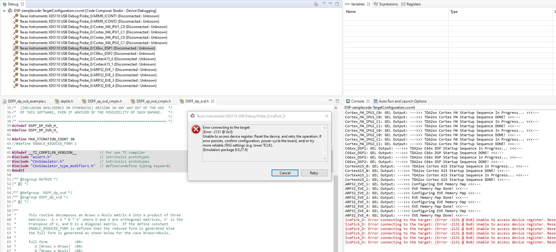
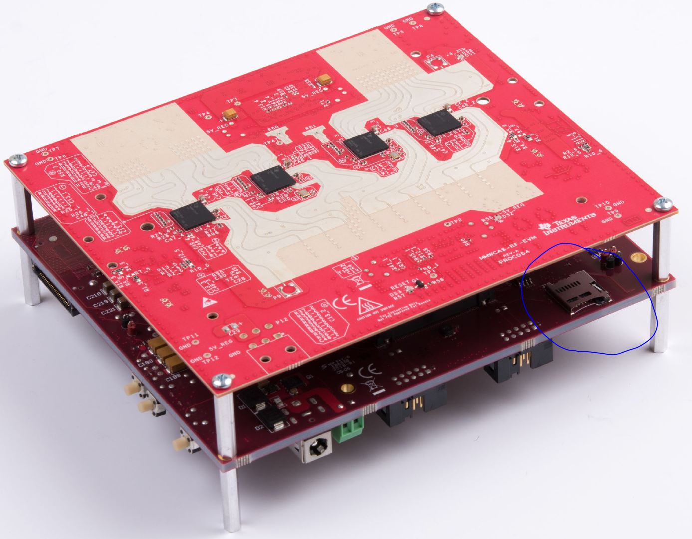
I tried to begin debugging thee TDA2 Cascade EVM with XDS110. I got the below error. Please advice how to proceed.

Thanks,

--Khai

-----[Print the board config pathname(s)]------------------------------------

C:\Users\khai.trinh\AppData\Local\Texas Instruments\
CCS\TI\0\2\BrdDat\testBoard.dat

-----[Print the reset-command software log-file]-----------------------------

This utility has selected a 100- or 510-class product.
This utility will load the adapter 'jioxds110.dll'.
The library build date was 'May 30 2018'.
The library build time was '23:03:35'.
The library package version is '8.0.27.9'.
The library component version is '35.35.0.0'.
The controller does not use a programmable FPGA.
The controller has a version number of '5' (0x00000005).
The controller has an insertion length of '0' (0x00000000).
This utility will attempt to reset the controller.
This utility has successfully reset the controller.

-----[Print the reset-command hardware log-file]-----------------------------

The scan-path will be reset by toggling the JTAG TRST signal.
The controller is the XDS110 with USB interface.
The link from controller to target is direct (without cable).
The software is configured for XDS110 features.
The controller cannot monitor the value on the EMU[0] pin.
The controller cannot monitor the value on the EMU[1] pin.
The controller cannot control the timing on output pins.
The controller cannot control the timing on input pins.
The scan-path link-delay has been set to exactly '0' (0x0000).

-----[An error has occurred and this utility has aborted]--------------------

This error is generated by TI's USCIF driver or utilities.

The value is '-233' (0xffffff17).
The title is 'SC_ERR_PATH_BROKEN'.

The explanation is:
The JTAG IR and DR scan-paths cannot circulate bits, they may be broken.
An attempt to scan the JTAG scan-path has failed.
The target's JTAG scan-path appears to be broken
with a stuck-at-ones or stuck-at-zero fault.

[End: Texas Instruments XDS110 USB Debug Probe_0]

  • Hi,

    I skipped the connection test and launched the Target Configuration file. It went further. But when I tried to connect to the DSP1 (right click->Connect Target), I got the attached failure.

    Thanks,

    --Khai

  • Hi Khai,

    can you check if this can help you:

    Regards,

    Yordan

  • In addition, this looks like a HW issue to me. Try disassembling the EVM and putting it back together with all parts properly fasten. Then create a new target configuration and try again. 

  • My TDA2 Processor board is working fine. I am running radar use case on it and it works. Just now i need to debug it with debugger that failed to connect. It could be the debugger problem.

    Thanks,

    --Khai

  • If you are booting an OS, that can also prevent it from initializing the JTAG. Are you trying to connect to a bare metal EVM (just initialized after ROM code)? 

  • I am running TI rtos. If that's a problem, how do I just run rom code. What's the step? Right now, I am running off a SIM card that contains the processor sdk appimage and trying to debug am offline algorithm by loading the application on to the c66. If that's not the proper step, please advice...

    Thanks,

    Khai

  • Right, if you want JTAG, you shouldn't be booting software/OS from MMC/flash/another unit because it's messing with JTAG settings, and probably disabling it. If you want to debug the RTOS, the source/binary should be loaded via CCS when you connect to target. See device "Initialization" chapter in the TRM on how to not boot from external media but from ROM only. 

  • Please provide the doc. Does that mean for the processor board, I simply apply power without inserting the SIM card?

    Thanks,

    Khai

  • Khai Trinh said:
    Please provide the doc.

    Here is the TRM for details:  

    Khai Trinh said:
    Does that mean for the processor board, I simply apply power without inserting the SIM card?

    Generally speaking yes, but double-check your SYS_BOOT pins.

    Try it and let us know if you can connect to the device without booting anything first. 

    thanks,

    Alex

  • Hi Alex,

    No, Same thing.

    Removed the appimage SIM and power up the board, run the target config test, same error. Click reset button on the board, rerun target config test, same result. Can we schedule a debug session?

    Thanks,

    --Khai

  • Hello Khai,

    Wait, I know it says EVM, but I don't see a SIM slot depicted in the general EVM documentation. Is this a custom board you are using? If so could be a problem with JTAG schematics. Another way is to play with the DIP switch to try different boot modes.

    thanks,

    Alex

  • Hi Alex,

    Yes this is the factory TDA2 EVM Processor Board.

    See attached pic.

  • OK this still looks like a HW issues to me. Assuming your JTAG is tested good with other boards, can you give us the EVM serial numbers and we will check with the manufacturer. 

    thanks,

    Alex

  • Khai

    Did you make sure the SYSBOOT pins are set correctly?

    Thanks and Regards

    Piyali

  • HI Piyali,

    When you guys give instruction to the solution, can you be not assume that the person who asked the question knows or understand what you are referring to? The more specific you are, the shorter the thread it will be. This will save a hec lot of both your time and ours. We didn't design the HW/SW. So when you say SYSBOOT pin, you assume that I know exactly what you are referring to. Please supplement you answer with specific pic or doc that show me where to set this pin on the board would be greatly helpful and this thread can be closed. Now I have to hunt for the Doc that describe where the hec on the board this pin is and so far I have no luck in hunting it down and thus the thread continues on for yet another couple of back and forth.

    Just my take on most of the responses from your team. You support forum is great but you guys didn't take the time to raise the quality of the responses to cut it short. The goal of your support team should be to lessen your burden in spending a lot of time in support by addressing the questions to bring them to the bottom of it.

    Thanks

  • SO i found the doc that given to me by Alex that described SYSBOOT in 31.2.4 Sysboot Configuration.

    So looks like there are two main booting type - Peripheral or MEM booting. I assume I need it to be in Peripheral mode. But then how to set the board to be in USB booting mode? Is there a dip switch taken out to the board level to set this boot mode?

    Thanks,

    --Khai

  • Hello Khai,

    Apologize if we've been vague, but we also expect the from the user to be familiar with documentation first. When we post a reply, we assume that's already been done and they have read the docs (at least the important stuff like booting the device (like I said found in the initialization chapter in the technical reference manual)). We cannot possibly describe all things documentation explains here. So, you should be familiar and know where to look for information first before asking a question here. For example, get to know the SDK docs (found in the docs folder of the SDK for the device), and TRM (Technical reference manual) and DM (Data Manul) found on ti.com product page (for your processor: https://www.ti.com/product/TDA2P-ACD/technicaldocuments). On that product page, there are also many other custom docs for specific topics that may be needed one time or another. 

    Now on to the last question. What we suggest is to set your pins in debug mode and see if you can finally connect. Here is an excerpt from VisionSDK_UserGuide_TDA2px.pdf found in "VisionSDK\vision_sdk\docs\UserGuides" folder. 

    Let us know the results please, thanks!

    Alex

  • Hi Alex,

    The XDS100 debugger i used  was aml-function. I just purchased the 560v2 and it worked like a charm.

    With the 560v2, I ran the code with the SIM card that has the entire use case application and running, then run the debugger and tapped into the DSP device that I would like to debug on, load the debug symbol for the DSP, inserted some break point and resume the DSP and off I am running.

    So thanks for the help. I guess boot mode setting isn't necessary. It might be necessary if running without SIM. But I need to run with SIM to debug along with the whole application

    Regards,

    --Khai

  • Hello Khai,

    Great to hear! So a broken JTAG then. Thanks for sharing your finds as well for others with similar issues to see.

    Closing this thread.  

    thanks,

    Alex