Part Number: AM4378
Other Parts Discussed in Thread: AM4372, SYSCONFIG
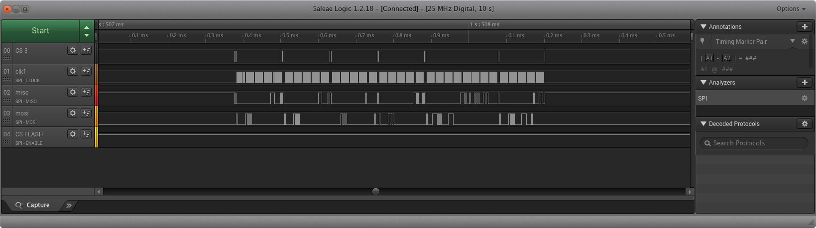
We have a custom made board running an am437x device. We have two peripherals connected to SPI0 on CS0 and CS3.
They are connected as follows:
mux.c:
static struct module_pin_mux spi_flash_pin_mux[] = {
{OFFSET(spi0_d0), (MODE(0) | RXACTIVE | PULLUDDIS)}, /* SPI0_D0 */
{OFFSET(spi0_d1), (MODE(0) | PULLUDDIS)}, /* SPI0_D1 */
{OFFSET(spi0_cs0), (MODE(0) | PULLUP_EN | PULLUDEN)}, /* SPI0_CS0 */
{OFFSET(cam1_hd), (MODE(2) | PULLUP_EN) | PULLUDEN}, /* SPI0_CS3 */
{OFFSET(spi0_sclk), (MODE(0) | RXACTIVE | PULLUDDIS)}, /* SPI0_SCLK */
{-1},
};
dts:
flash_memory_spi_pins_default: flash_memory_spi_pins_default {
pinctrl-single,pins = <
AM4372_IOPAD(0x950, PIN_INPUT | MUX_MODE0) /* (P23) spi0_sclk.spi0_sclk */
AM4372_IOPAD(0x954, PIN_INPUT | MUX_MODE0) /* (T22) spi0_d0.spi0_d0 */
AM4372_IOPAD(0x958, PIN_OUTPUT | MUX_MODE0) /* (T21) spi0_d1.spi0_d1 */
AM4372_IOPAD(0x95c, PIN_OUTPUT_PULLUP | MUX_MODE0) /* (T20) spi0_cs0.spi0_cs0 */
AM4372_IOPAD(0x9d4, PIN_OUTPUT_PULLUP | MUX_MODE2) /* (AD25) cam1_hd.gpio4[9] */
>;
};
&spi0 {
u-boot,dm-spl;
pinctrl-names = "default";
pinctrl-0 = <&flash_memory_spi_pins_default>;
status = "okay";
ti,spi-num-cs = <4>;
flash: spi_flash@0 {
#address-cells = <1>;
#size-cells = <1>;
u-boot,dm-spl;
u-boot,dm-pre-reloc;
compatible = "jedec,spi-nor";
reg = <0>; /* Chip select 0 */
spi-max-frequency = <24000000>;
};
dev_xxx@3 {
compatible = "dev_xxx-spi";
reg = <3>;
spi-max-frequency = <400000>;
};
};
U-boot version:
U-Boot 2019.10-rc1-g773766f6f1-dirty (May 05 2020 - 12:47:27 +0300)
arm-linux-gnueabihf-gcc (GNU Toolchain for the A-profile Architecture 8.3-2019.03 (arm-rel-8.36)) 8.3.0
GNU ld (GNU Toolchain for the A-profile Architecture 8.3-2019.03 (arm-rel-8.36)) 2.32.0.20190321
Problem is that when SPI-memory is probed (CS0) it also pulls the chip select for CS3 so that both peripherals gets activated at the same time.
I can go around this by changing the order the peripherals are probed and hacking the SPI driver. This, however, means that my hack will need to be applied to any future updates we make to U-boot.
The reason it fails for us is that the polarity register for CS3 of SPI0 (MCSPI0->MCSPI_CH3CONF->EPOL) defaults to active high after MCSPI software reset(we need the opposite). For it to work the MCSPI_CH(X)CONF register for each CS used has to be initialized with the correct values prior to trying to access any of the peripherals. But the driver does not seem to operate like this. Instead, it only updates the MCSPI_CH(X)CONF of the peripheral that is currently being accessed. So for us it works like this:
Step 1) probe cs0 - This correctly configures cs0 but operation fails because cs3 is configured wrong.
Step 2) probe cs3 - This correctly configures cs3 and because cs0 is still configured correctly the peripheral is successfully probed
Step 3) probe cs0 - Because both cs0 and cs3 are now correctly configured also this peripheral works.
In reality, because of a bug (?), step 2 has to executed twice for it to work.
The reason that step 2 has to rpeated twice is that in:
spi-uclass.c
the function:
int dm_spi_claim_bus(struct udevice *dev)
(indirectly) calls:
static int omap3_spi_set_mode(struct udevice *dev, uint mode)
before it calls:
static int omap3_spi_claim_bus(struct udevice *dev)
The omap3_spi_claim_bus is where the "to-be-used" cs is updated in the private data structure used by the SPI driver.
The omap3_spi_set_mode is the function that actually updates the chip-select related register values.
Since omap3_spi_set_mode is called before omap3_spi_claim_bus the actual updating of the register is not performed until the next call to dm_spi_claim_bus. Probably not as intended?
The above also applies to:
static int omap3_spi_set_speed(struct udevice *dev, unsigned int speed)
which is also called before omap3_spi_claim_bus resulting in the speed being updated for the previously used chip-select.
This can be mitigated with a small hack:
static int omap3_spi_claim_bus(struct udevice *dev)
{
struct udevice *bus = dev->parent;
struct omap3_spi_priv *priv = dev_get_priv(bus);
struct dm_spi_slave_platdata *slave_plat = dev_get_parent_platdata(dev);
priv->cs = slave_plat->cs;
priv->freq = slave_plat->max_hz;
_omap3_spi_claim_bus(priv);
_omap3_spi_set_mode(priv); <-- Add this here
_omap3_spi_set_speed(priv); <-- Add this here
return 0;
}
static int omap3_spi_set_speed(struct udevice *dev, unsigned int speed)
{
struct omap3_spi_priv *priv = dev_get_priv(dev);
priv->freq = speed;
// _omap3_spi_set_speed(priv); <-- Comment out
return 0;
}
static int omap3_spi_set_mode(struct udevice *dev, uint mode)
{
struct omap3_spi_priv *priv = dev_get_priv(dev);
priv->mode = mode;
// _omap3_spi_set_mode(priv); <-- Comment out
return 0;
}
So, with a little hacking and creative probing I can get our device to work properly. The question is, should this work out of the box without any hacking?
Is TI u-boot SPI driver intended to support multiple peripherals(multiple chip-selects) on the same bus?
If so, did I configure it wrong or is the driver broken?
If possible I would prefer a solution where I do not have to patch the low-level driver.