This thread has been locked.

If you have a related question, please click the "Ask a related question" button in the top right corner. The newly created question will be automatically linked to this question.

TDA2EXEVM: How to configure the DIP switch of video config (SW3) and enable Aptina camera via I2C

Part Number: TDA2EXEVM

Hi,

We are working enable a customized Aptina camera module(AR0140 w/ parallel interface output) which connected with TDA2X Vision board.

The board information as following:

Vision SDK Version    : [REL_VISION_SDK_03_07_00_00]
FVID2 Version         : [FVID_02_01_00_01]
BSP Version           : [PDK_01_10_03_xx]
Platform              : [EVM]
SOC                   : [TDA2XX]
SOC Revision          : [ES2.0]
Board Detected        : [Vision]
EEPROM Board Info Header Mismatch!!
Base Board Revision   : [REV A]
Daughter Card Revision: [REV D]

As the user guide of  VisionSuper28 Vision Application Board (pg#5), 

we connected the sensor board  with I2C_2_ (SDA/CLK) and Expansion connector (MUX1 MUX2, VIN1A).

ps: default CPLD image.

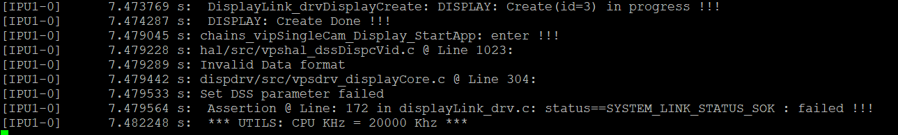
we tried configure the DIP switch of Video Config (SW3), but it showed the I2C error message when initialize the sensor configuration (1280*720@30fps):

Could you teach me how to solve the issue and preview camera image? Thanks.

[IPU1-0]      7.487464 s: src/bsp_deviceI2c.c @ Line 1568:
[IPU1-0]      7.487555 s: Bus busy detected recover I2C bus !!!
[IPU1-0]      7.487647 s: src/bsp_deviceI2c.c @ Line 923:
[IPU1-0]      7.487738 s:  I2C2: DEV 0x10: WR 0x301a = 0x00d9 ... ERROR !!!
[IPU1-0]      7.487891 s: src/bsp_deviceI2c.c @ Line 945:
[IPU1-0]      7.487952 s:  I2C2: Error timeout 3 ms!!!
[IPU1-0]      7.690721 s: src/bsp_deviceI2c.c @ Line 1568:
[IPU1-0]      7.691026 s: Bus busy detected recover I2C bus !!!
[IPU1-0]      7.691118 s: src/bsp_deviceI2c.c @ Line 923:
[IPU1-0]      7.691209 s:  I2C2: DEV 0x10: WR 0x301a = 0x30d8 ... ERROR !!!
[IPU1-0]      7.691301 s: src/bsp_deviceI2c.c @ Line 945:
[IPU1-0]      7.691392 s:  I2C2: Error timeout 4 ms!!!

BRs,

Sam. Hsieh

  • Could you please first try to access this board from i2c utility?

    Rgds,

    Brijesh

  • Hi Brijesh,

    I observed the example of i2c utility.

    Could you teach me how to build the image which included non-baremetal OS? Thanks.

    ps. FILE: component.mk

     # Components included for non-baremetal OS
    298 ifneq ($(BUILD_OS_TYPE), baremetal)

    regards,

    Sam.

  • Hi Sam,

    You could just build this example using make -s bsp_examples_i2c_utility command.

    Rgds,

    Brijesh

  • Hi Brijesh,

    Thank you for your feedback.

    It shows that error message when execute "make -s bsp_examples_i2c_utility"

    make: *** bsp_examples_i2c_utility: No such file or directory.  Stop.

    regards,

    Sam.

  • Hi Sam,

    From which folder are you trying to build?

    I am able to build it from pdk/packages/ti/build folder. Since this is PDK example, you need to build it from PDK build folder.

    Rgds,

    Brijesh 

  • Hi Brijesh,

    Oh. I got it.

    I made in a mistake in which build the example from vision_sdk/build folder.

    I observed that the output image ( ti/binary/bsp_examples_i2c_utility/bin/tda2xx-evm/bsp_examples_i2c_utility_ipu1_0_release_BE.appimage).

    which must load&run the image via CCS.  Is it right ?

    BRs,

    Sam Hsieh

  • Hi Sam,

    This example you need to run it using CCS on one of the IPU core. Please refer to PDK userguide to understand how to run example on CCS.

    Rgds,

    Brijesh  

  • Hi Brijesh,

    Understood,

    Thank you for your support.

    BTW, Could you teach me how to know I2C_1 (SDA) connect which GPIO base & PIN? Thanks.

    ps. trace from source code, the reset signal of Aptina' Sensor  connected GPIO6.[11]. via the Expansion connector of application vision Board.

    BRs,

    Sam. Hsieh

  • Hi Sam,

    This needs to be checked in schematic. Could you please check it in schematic?

    Rgds,

    Brijesh

  • Hi Brijesh,

    Thank you for your suggestion.

    I have configured successfully the APTINA sensor (AR0144)  via I2C1 interface, and access the Chipset ID.

    Due to the sensor output  as 10-bits Bayer raw image (Monochrome),

    the usercase of vip_single_cam_opencvcanny  just display one half of image on HDMI panel.

    As for the ChainsCommon_SetVidSensor() function, I configured:

         pPrm->standard       = SYSTEM_STD_720P_60;
        pPrm->dataformat    = SYSTEM_DF_BAYER_GRBG;
        pPrm->videoIfWidth  = SYSTEM_VIFW_10BIT;
        pPrm->fps                  = SYSTEM_FPS_60;
        pPrm->numChan      = numCh;
        pPrm->isLVDSCaptMode = FALSE;

    It seems that there is some problem in format mismatch between vpscore and capture (VIP).

    Could you help teach me how to solve the display issue ?

    BRs,

    Sam.

    regards,

    Sam Hsieh

  • Hi Sam,

    Great, good to know that you are now able to access AR0144 and also able to capture the data.

    I would first suggest to dump one capture frame and check if the received frame is correct and is as expected in terms of frame size.  

    Frame/Buffer size is typically same for YUV422 and 10bit bayer data.. display should be able to display atleast full screen, although quality may not be good. 

    Regards,

    Brijesh 

  • Hi Brijesh,

    Thank you for your suggestion.

    As I try to configure the format of (FVID2 &sensor driver)

    FVID2_DF_YUV422I_UYVY = 0x0000,         /**< YUV 422 Interleaved format - UYVY. */

    FVID2_DF_YUV422SP_UV

    FVID2_DF_YUV422P

    It just display a half of image on the screen.

    I guess that the format should be for the color space image,

    the monochrome/gray image should be Y planar only without U and V (chrominance; color).

    It means that FVID2 should handle the image data with a special method.

    Could you help teach me how to validate the data whether if it be correct for each Link (Capture, Alg_link, Display)?


    BRs,

    Sam.

  • Hi Sam,

    As i said, format is correct. Since VIP is a video port, we are just configuring it to capture 10bit data as if it is YUV422 and store it in 16bit container. So this is fine. 

    Fvid2 cannot handle/convert the data format, This needs to be done by one of the HW module. But monochrome data could be processed in DSP only. 

    If you just directly connect it to display, display will just it as if it is YUV422. But even in this case, height should not be half. 

    This is why i was suggesting, can you try dumping a frame from the capture and analyze it offline?

    Regards,

    Brijesh

  • Hi Brijesh,

    Thank you for your comment.

    I confirmed that the input/output dataformat (In/Out: SYSTEM_DF_YUV422P, SYSTEM_DF_YUV420SP_UV) of CaptureLink is correct

    which as configured at ChainsCommon_SingleCam_SetCapturePrms().

    [IPU1-0]     11.415970 s: CaptureLink_drvProcessData: CAPTURE(0): (numFrame=1, infmt=0x6, outfmt=0x7)!!!
    [HOST  ]     11.416305 s: AlgorithmLink_opencvCannyProcess: Input format=0x0, pitch=0x500, Output format=0x7, pitch[0..1]=0x500 0x500

    But the dataformat of AlgorithmLink_opencvCannyProcess() isn't as expected.

    It seems that there is a problem in data format mismatch, 

    Does it be the same data format (SYSTEM_DF_YUV420SP_UV ) during Algorithmlink?

    BTW, the height of image is correct, the width of image is half of sensor output.

    I understood that the function is created by AlgorithmLink_pluginCreate(),

    I don't know how to pass the created parameter from Utils_msgGetPrm(pMsg)
    Could you help instruct me how to pass the of pCreateParams to AlgorithmLink_opencvCannyCreate( ) function? Thanks.

    I observed that the Alg_OpenCVCannyProcess() function handle the wordwidth on the dataformat.

     if(dataFormat == SYSTEM_DF_YUV422I_YUYV)
        {
            numPlanes = 1;
            wordWidth = (width*2)>>2;
        }
        else if(dataFormat == SYSTEM_DF_YUV420SP_UV)
        {
            numPlanes = 2;
            wordWidth = (width)>>2;
        }

    BRs.

    Sam Hsieh

  • Hi Sam,

    I am really not sure about canny algorithm. If you bypass canny algorithm and connect capture directly to display, does it work fine?

    Regards,

    Brijesh

  • Hi Brijesh,

    I ran the usecase of "vip_single_cam_view", it just displayed green screen without no image data.

    I confirmed that both the CaptureLink and DisplayLink called drvprocessdata() function when receive an  SYSTEM_CMD_NEW_DATA command.

    and the following statistics also work fine.

    but I observed that a surprising phenomenon:

    both the pVideoFrame->chInfo.width, pVideoFrame->chInfo.height are zero on the DisplayLink when ran the usecase of vip_single_cam_view .

    the pVideoFrame->chInfo.width(0x500) , pVideoFrame->chInfo.height (0x2d0) are ok on the DisplayLink when ran the usecase of opencanny.

    I am not sure whether if it is related to the output format (isChInfoChangeValid flag)?

    BRs,

    Sam Hsieh.

    ===========================================================================

    [IPU1-0]     17.756542 s:  ### CPU [IPU1-0], LinkID [ 74],
    [IPU1-0]     17.756603 s:
    [IPU1-0]     17.756664 s:  [ CAPTURE ] Link Statistics,
    [IPU1-0]     17.756725 s:  ******************************
    [IPU1-0]     17.756786 s:
    [IPU1-0]     17.756816 s:  Elapsed time       = 3900 msec
    [IPU1-0]     17.756877 s:
    [IPU1-0]     17.756908 s:  New data Recv      =  30.0 fps
    [IPU1-0]     17.756999 s:  Get Full Buf Cb    =  30.0 fps
    [IPU1-0]     17.757121 s:  Put Empty Buf Cb   =  29.48 fps
    [IPU1-0]     17.757213 s:  Driver/Notify Cb   =  30.0 fps
    [IPU1-0]     17.757304 s:
    [IPU1-0]     17.757335 s:  Input Statistics,
    [IPU1-0]     17.757396 s:
    [IPU1-0]     17.757426 s:  CH | In Recv | In Drop | In User Drop | In Process
    [IPU1-0]     17.757518 s:     | FPS     | FPS     | FPS          | FPS
    [IPU1-0]     17.757579 s:  --------------------------------------------------
    [IPU1-0]     17.757670 s:   0 |  29.48      0. 0      0. 0          29.48
    [IPU1-0]     17.757792 s:
    [IPU1-0]     17.757823 s:  Output Statistics,
    [IPU1-0]     17.757884 s:
    [IPU1-0]     17.757914 s:  CH | Out | Out     | Out Drop | Out User Drop
    [IPU1-0]     17.758006 s:     | ID  | FPS     | FPS      | FPS
    [IPU1-0]     17.758067 s:  ---------------------------------------------
    [IPU1-0]     17.758158 s:   0 |  0     30. 0     0. 0      0. 0
    [IPU1-0]     17.758250 s:
    [IPU1-0]     17.758311 s:  [ CAPTURE ] LATENCY,
    [IPU1-0]     17.758372 s:  ********************
    [IPU1-0]     17.758433 s:
    [IPU1-0]     17.758524 s:
    [IPU1-0]     17.758585 s:  ### CPU [IPU1-0], LinkID [ 77],
    [IPU1-0]     17.758646 s:
    [IPU1-0]     17.758677 s:  [ DISPLAY ] Link Statistics,
    [IPU1-0]     17.758738 s:  ******************************
    [IPU1-0]     17.758799 s:
    [IPU1-0]     17.758860 s:  Elapsed time       = 3902 msec
    [IPU1-0]     17.758921 s:
    [IPU1-0]     17.758951 s:  New data Recv      =  29.72 fps
    [IPU1-0]     17.759012 s:  Driver/Notify Cb   =  59.96 fps
    [IPU1-0]     17.759104 s:
    [IPU1-0]     17.759134 s:  Input Statistics,
    [IPU1-0]     17.759195 s:
    [IPU1-0]     17.759226 s:  CH | In Recv | In Drop | In User Drop | In Process
    [IPU1-0]     17.759318 s:     | FPS     | FPS     | FPS          | FPS
    [IPU1-0]     17.759409 s:  --------------------------------------------------
    [IPU1-0]     17.759470 s:   0 |  29.98      0. 0      0. 0          29.98
    [IPU1-0]     17.759623 s:
    [IPU1-0]     17.759653 s:  [ DISPLAY ] LATENCY,
    [IPU1-0]     17.759714 s:  ********************
    [IPU1-0]     17.759775 s:  Local Link Latency     : Avg =     42 us, Min =     30 us, Max =    213 us,
    [IPU1-0]     17.759897 s:  Source to Link Latency : Avg =    113 us, Min =     91 us, Max =    305 us,
    [IPU1-0]     17.759989 s:
    [IPU1-0]     17.760050 s:  Display UnderFlow Count = 0
    [IPU1-0]     17.760111 s:
    [IPU1-0]     17.760141 s:  CPU [  IPU1-0], LinkID [ 23], Link Statistics not available !
    [IPU1-0]     17.760507 s:
    [IPU1-0]     17.760568 s:  ### CPU [IPU1-0], LinkID [ 78],
    [IPU1-0]     17.760629 s:
    [IPU1-0]     17.760660 s:  [ DISPLAY ] Link Statistics,
    [IPU1-0]     17.760721 s:  ******************************
    [IPU1-0]     17.760782 s:
    [IPU1-0]     17.760843 s:  Elapsed time       = 3930 msec
    [IPU1-0]     17.760904 s:
    [IPU1-0]     17.760934 s:  Driver/Notify Cb   =  60.5 fps
    [IPU1-0]     17.760995 s:
    [IPU1-0]     17.761056 s:  Input Statistics,
    [IPU1-0]     17.761087 s:
    [IPU1-0]     17.761148 s:  CH | In Recv | In Drop | In User Drop | In Process
    [IPU1-0]     17.761209 s:     | FPS     | FPS     | FPS          | FPS
    [IPU1-0]     17.761300 s:  --------------------------------------------------
    [IPU1-0]     17.761392 s:   0 |   0.25      0. 0      0. 0           0.25
    [IPU1-0]     17.761544 s:
    [IPU1-0]     17.761575 s:  [ DISPLAY ] LATENCY,
    [IPU1-0]     17.761636 s:  ********************
    [IPU1-0]     17.761666 s:  Local Link Latency     : Avg =    214 us, Min =    214 us, Max =    214 us,
    [IPU1-0]     17.761788 s:  Source to Link Latency : Avg = 669798 us, Min = 669798 us, Max = 669798 us,
    [IPU1-0]     17.761971 s:
    [IPU1-0]     17.762002 s:  Display UnderFlow Count =0

  • ok, green screen could be due to buffer is completely 0 because green is complete 0x0 in buffer. 

    Yes, buffer width and height could also be a problem. But we do have capture -> display examples, which work fine. So i am doubting that the capture output is complete filled with 0x0. When you have canny in between, was the output atleast viewable? 

    Can you dump one captured frame and view it offline?

    Rgds,

    Brijesh

  • Hi Brijesh,

    I tried to save Capture frame into MMC/SD from the Capture Link, but it failed,

    I met a problem in which the "chains_vipSingleCam_DisplayObj" can't refer to the CaptureLink_Obj.

    at the same time, FVID2_frame be separated Y, U,V on different planes (field 0, 1);

    Because the output of AR0144 sensor is 10-bits raw image without ISP processing,

    Could you tell me which task sent "SYSTEM_CMD_NEW_DATA" cmd to the CaptureLink_tskRun?

    BRs,

    Sam Hsieh

  • Hi Sam,

    Since it is RAW data, it cannot be displayed. VIP can capture it in 16bit container, but DSS can display only YUV or RGB data. 

    Also since this is RAW data, it will be available only on frame->addr[0][0] index.

    Depending on your chain, the new_data command from capture link will be sent out to next link in the chain..  

    Regards,

    Brijesh

  • Hi Brijesh,

    I don't understand clearly the VIP and DSS mechanisms. 

    Does the FVID2 manager handle color space (data format conversion)?

    If the DSS just receives YUV or RGB data frame,  could FVID2 not support the feature?

    BTW, it's amazed that the same CaptureLink and DisplayLink.

    Why does it display a half image on screen via canny ALG?

    BRs,

    Sam Hsieh

  • Hi Sam,

    No, FVID2 is just SW interface. It can't do color space conversion. It just provides SW interface to access VIP and DSS modules..

    But does canny support RAW data processing? Could you please check in the code? 

    If it just supports YUV422 or YUV420 formats, the output will not be correct.

    Rgds,

    Brijesh 

  • Hi Brijesh,

    Sorry! I made a mistake in the FVID interface, it should be VPSCORE configure VIP path which handle data conversion.

    From the function of VpsCore_vipPathSetConfig() (file: ti_components/drivers/pdk_01_10_03_07/packages/ti/drv/vps/src/vpslib/captcore/src/vpscore_vip.c)

    it seems that handle the data frame conversion.

    BTW, I observed that it default defined these flags of VPS_VIP_BUILD, VPS_VPE_BUILD, VPS_DSS_BUILD in the make rule,

    but the VPS_CAPT_BUILD is not defined.

    Is there any solution to handle data conversion (like duplicate a Y plane frame addr[0][1] )? 

    BRs,

    Sam Hsieh


    regards,

    Sam.

  • Hi Sam,

    VIP can do data conversion from YUV to RGB and vice versa, but it cannot convert from RAW to YUV/RGB format.

    Rgds,

    Brijesh

  • Hi Brijesh,

    Could you help point out which function of VIP code handle data conversion?

    BTW, I captured the raw image frame during Capture link process as the attached, it seems that just Y frames be included.

    Is it possible to add a patch to support the function of from RAW to YUV/RGB format?

    BRs,

    Sam Hsiehdump files.rar

  • Hi Sam,

    Could you please help us understand what you are trying to do?

    CSC functionality of VIP is explained in the TRM. 

    You would require ISP to convert RAW to RGB.

    Rgds,

    Brijesh

  • Hi Brijesh,

    We would like to use the monochrome camera to calculate the distance map (via algorithm).

    As the TRM, I understood the CSC functionality of VIP.

    ../../../../../_images/VIP-block-diagram.png

    From the HW feature, it could support the separate 24-bit video ports for parallel RGB/YUV/RAW (or BT656/1120) data.

    As the color space converter (CSC) described in http://software-dl.ti.com/processor-sdk-linux/esd/docs/latest/linux/Foundational_Components/Kernel/Kernel_Drivers/Camera/VIP.html

    As current the design, we have no intention to add ISP besides cost  and thermal concern (dimension limitation).

    BRs,

    Sam.

  • Hi Sam,

    For Monochrome input, you could VIP to capture data, but it can't do any conversion. Once it is captured, you could run your algorithm to calculate distance map. But you will not be able to display these, as display supports only YUV or RGB data. In order to display, either you need to convert it into YUV or RGB using some ISP, or you display it as luma only data, provide chroma buffer filled with 0x80..

    Rgds,

    Brijesh

  • Hi Brijesh,

    Thank you for your explanation & suggestion.

    As for display it as luma only data, filled with 0x80 in chroma buffer.

    I observed that there is a Utils_memFrameAlloc() function of  ../links_fw/src/rtos/utils_common/src/utils_mem.c

    during GrpxSrcLink_drvCreate() called which will add a chroma offset to chroma buffer.

    But I don't know how/where to filled with 0x80?

    Could you help teach me how to implement the function in GrpxSrcLink (Display Link)? Thanks.

    BRs,

    Sam Hsieh

  • Hi Sam,

    What you could do is,

    You could add support for Luma only or RAW format in the display link. 

    When you RAW format as input format in the display link, allocate addition buffer in the display with width*height/2 size and fill it up with 0x80.

    Now configure dss pipeline for YUV420 format and when you could get input buffer, this input buffer along with the chroma buffer give it to the driver as YUV420 buffer.  Display will display it as normal YUV420 data, but since chroma buffer is all 0x80, it will just display as grey screen..

    Rgds,

    Brijesh

  • Hi Brijesh,

    Thank you for your suggestion.

    I filled  into U plane with 0x80 (pFrame->addr[0][1]) when CaptureLink handle captured data.

    It could display a half of grey screen, the issue of green screen is gone.

    but I don't understood clearly how to xfer the field0/field1 frame from Capturelink to DisplayLink.

    Could you teach me how to fix the issue of a half of screen ? Thanks.

    ps. usecase: vip_single_cam_view

    BRs,

    Sam Hsieh

  • Hi Sam,

    Field is required only for interlaced capture. Most of the cameras uses progressive mode. So no need to worry about fields.  

    Regards,

    Brijesh

  • Hi Brijesh,

    Understood.

    As the function of ChainsCommon_SingleCam_SetCapturePrms() configured the captureInWidth=1280, captureInHeight=720,

    and the ChainsCommon_SetDisplayPrms().

    But it still just display one-half image on screen as the attached.

    it seems that there are a half frame data be truncated during VIP parsing frame.

    Could you help explain how to parse the raw monochrome image frame from sensor output via parallel interface? 

    BRs,

    Sam.

  • Hi Sam,

    I am sorry, what is your output format from VIP? is it RAW10 or RAW8?

    Regards,

    Brijesh 

  • Hi Brijesh,

    The output format is RAW10.

    BRs,

    Sam Hsieh

  • And how is it stored in memory? is it stored in 16bit container in unpacked format? 

    Can you save capture output and view it offline in some hex viewer and check if the data is 10bit or 8bit? also is the full line captured in the buffer? 

    Can you also check if the pitch/line-offset provided to the driver is correct?

    Rgds,

    Brijesh

  • Hi Brijesh,

    BTW, as the function of vpsDrvCaptGetVipCoreSrcId() in file:

    .ti_components/drivers/pdk_01_10_03_07/packages/ti/drv/vps/src/vpsdrv/captdrv/src/vpsdrv_captureCore.c 

    Which described the slice1 PortA  just support FVID2_VIFW_8BIT/ FVID2_VIFW_16BIT/ FVID2_VIFW_16BIT (instObj->createPrms.videoIfWidth).

    It seems that there is a trick to convert the sensor format (from Bayer raw 10-bit to 16-bit in the VIP handling) then parsing Y frame.


    I'm a bit confused at the videoIfWidth & data format.

    Could you help teach me how to identify the createPrms.videoIfWidth for  sensorConfig or display data-format? Thanks.

    BRs,

    Sam Hsieh

  • Sam,

    Video Interface width (videoIfWidth) provides the interface size, ie 8bit, 16bit or 24bits. whereas dataformat provides format of the data ie YUV/RGB etc.. Both are different settings.. 

    What is black box in the above image? Do you have anyother module between sensor and VIP? 

    Rgds,

    Brijesh 

  • Hi Brijesh,

    I stored the captured frame (frame->addr[0][0]) into SD card via the API:

    ChainsCommon_Osal_fileWrite( fp, (UInt8*)ChainsCommon_Osal_getVirtAddr( (UInt32)Plane_bufaddr), frame_size); 

    but the content is wrong (0x00).

    At the same time, I observed that the following error message: does it related to the wrong frame ?  

    BRs,

    Sam Hsieh.

  • Hi Sam,

    The error is correct, since you are using RAW10 bit input, the interface size cannot be 8bit, so driver defaulting to 16bit..

    Does display still display half correct frame? If this is the case, then dumped file is not correct. 

    Do you have JTAG connectivity? 

    Rgds,

    Brijesh


  • Hi Brijesh,

    I understood the difference between the videoIfWidth and dataformat,

    but I don't know why it couldn't display a half of mono image after configured 10-bits VIP slice1/port (from 8-bit)

    It seems that there is some mismatching issue between Sensor output and CaptureLink.

    It observed that the input data format is 0x1e during DisplayLink handled (In DisplayLink_drvProcessData()).

    The Mono sensor just output 10-bit raw Y image data (W/O UV) on the TDA2X board,

    how VIP store data in the frame->addr[0][0] and frame->addr[0][1]) or all Y frames stored in addr[0][0] buffer?  

    Is it like as the following :

    BTW, we reserved  a JTAG interface on TDA2X board for connect CSS.

    There are no other module between SENSOR and VIP board.

    BRs,

    Sam Hsieh

  • Hi Sam,

    In this case, VIP stores data only using addr[0][0] memory. 

    0x1E data format is FVID2_DF_BGRA16_4444.. So that could be incorrect if you are not using GRPX link.

    Can you share frame size and data format for both VIP and DSS?

    Rgds,

    Brijesh

  • Hi Brijesh,

    I observed that the GRPX link is initiated & work fine

    .

    at the same time, the chains_vipSingleCam_Display_SetAppPrms() configured the dataFormat of GrpxSec.

    pUcObj->GrpxSrcPrm.grpxBufInfo.dataFormat = SYSTEM_DF_BGRA16_4444;  

    displayType = CHAINS_DISPLAY_TYPE_HDMI_1080P


    but the VIP configuration:  

     pObj->captureOutWidth=1280,

     pObj->captureOutHeight=720;

     pInstPrm->videoIfWidth  =   SYSTEM_VIFW_16BIT;

     pInprms->dataFormat =   SYSTEM_DF_YUV422P;

    regards,

    Sam Hsieh

  • ok, can you also please share display parameters?

  • Hi Brijesh,

    The display as following:

  • Hi Brijesh,

    Here are my configuration of  the vip_single_cam_view.

    BTW, the AR0144CS sensor could output 12-bit/10-bit data via parallel interface. defaults 12-bits (control by 0x31AC Reg.) 

    Could you help review which Params could result in the issue? Thanks.

  • Hi Sam,

    Can you try changing display format to also YUV422 and pitch to 2 times width? How doe it look in this case?

    I see format mismatch between capture and display, I am not sure if the half screen issue is due to format mismatch.. But can you make them same and check the output? 

    Regards,

    Brijesh 

  • Hi Brijesh,

    I tried to update the display format to YUV422 & 2 times width (YUV422P) which results in the assertion error,

    and it occurred the issue of upper half black screen and on the bottom half green screen when configured YUV422SP_UV.


    BRs,

    Sam Hsieh

  • Sam,

    Display supports only UYVY and YUYV YUV422 formats, can you please check if you have set it correctly?

    Rgds,

    Brijesh

  • Hi Brijesh,

    Understood, the Display link support YUV422/UYVY/YUYV format.

    I don't know why it could captured sensor raw image frame and display a-half image of screen  when VIP (slice1A port) configured the videoIfWidth as 8-bit,

    but it couldn't when configured 16-bits, and the all captured frame data are "0x00". 

    At the same time, it captured a frame which the size is 0xe1000 (921,600= 1280*720),  there are 640 bytes data, 640 bytes empty per SYNC.

  • Hi Sam,

    I am bit confused.

    Since your input is 10bit data, you cannot use 8bit interface. 8bit will just capture upper or lower 8bits and since the number of clock cycles remain same for 8bit, it will become half..

    Please use 16bit input interface. What do you see for 16bit interface? Does it capture full frame?

    rgds,

    Brijesh