This thread has been locked.

If you have a related question, please click the "Ask a related question" button in the top right corner. The newly created question will be automatically linked to this question.

AM6546: AM6546 USB 2.0 and 3.1 Models

Part Number: AM6546

Dear Team,

My self Akash, from Sienna ECAD Bangalore.

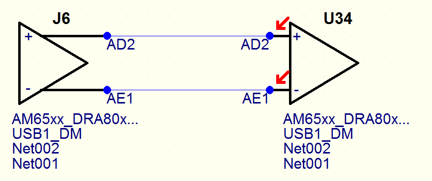
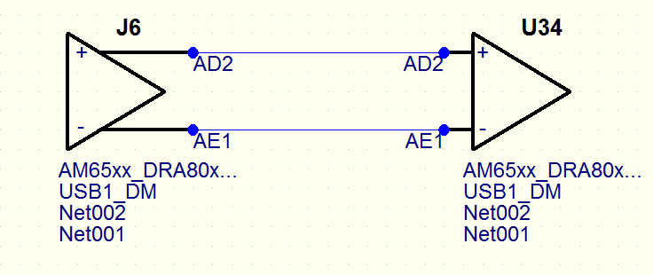
I was performing Signal integrity analysis for USB 2.0 interface considering AM6546 as driver.

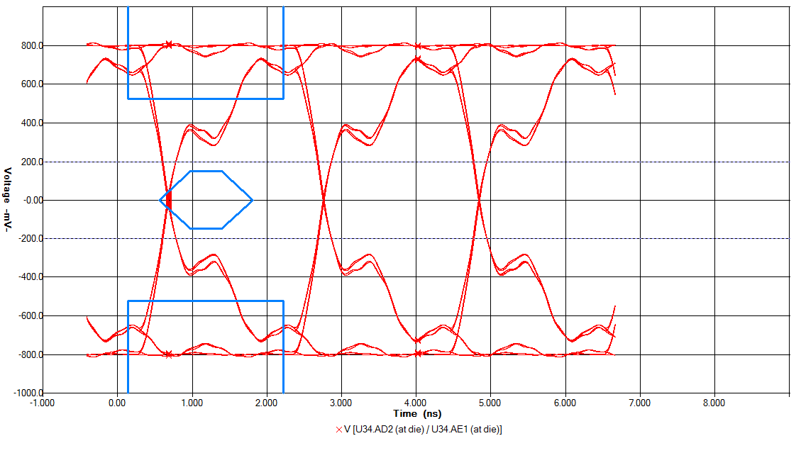
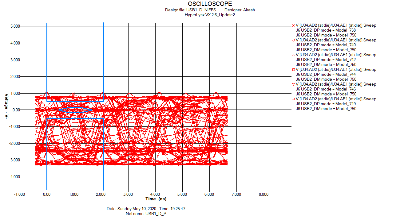
Even if we simulate the Signal integrity in Zero transmission path(just by considering driver and receiver), we are observing the eye is not meeting the required parameters, attaching the file for your reference.

Image of Zero transmission path.
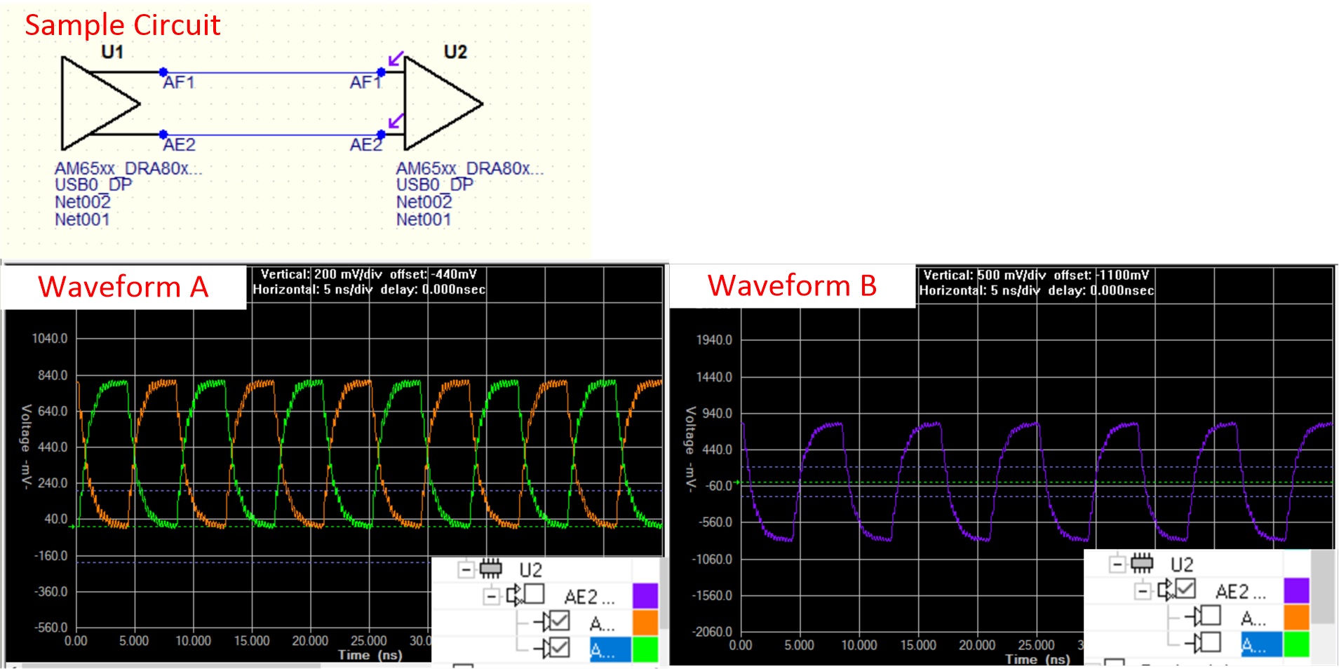
Wave forms

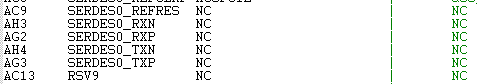
Also, for USB 3.1 we are noticing that there are no buffer models present in IBIS models.

Please let us know how to proceed further and over come these issues.

Warm Regards,

Akash Patil.

  • Dear Team,

    Is there any updates regarding USB signal query.

    Please let us know as early as possible, as we are planning to load the files to our FAB vendors.

    Kindly do the needful at the earliest.

    Warm Regards,

    Akash P

  • Akash, 

    We ran a quick check using Hyperlynx.  With the TX model configured as HSDP_TX and the RX model using FSRX we see a reasonable waveform.  

    Can you try that?  Also, can you share a basic waveform (~10 cycles) in addition to an eye diagram?

    Thanks,

    Kyle

  • Kyle,

    We had tried as per above mentioned configuration earlier and below were the results.

    Waveform is still exceeding the standard specified mask details.

    Schematic.

    Eye Diagram,

    Standard waveform,

    Also, please let us know which encoding technique was used while simulating at your end.

    Warm Regards,

    Akash P

  • I have create a simple Hyperlynx simulation with the AM65 IBIS model, and the USB differential input/outputs (as shown in customer's previous communication).

    Below is my sample circuit.  When looking at the signals themselves (Waveform A), you see the signals oscillate from 0v to 0.8v, as expected for HS USB driver.  However, when looking at the differential receiver (Waveform B), you see the signal oscillates +/-0.8V.  Again - this is an interpreted waveform (difference), not actually seen on the PCB.  If customer is looking at an eye diagram, they should use the signals themselves (as seen on the PCB), not the interpreted waveform generated by the differential receiver.

  • Is this issue resolved?