This thread has been locked.

If you have a related question, please click the "Ask a related question" button in the top right corner. The newly created question will be automatically linked to this question.

DRA829V: Can not receive/send characters to UART4

Part Number: DRA829V

Hi

Correct me if I am wrong. I hope I can make you understand the question.
So on the Jacinto7 EVM, we have a micro USB socket for the serial O/P and I/P for the MAIN domains. It has 4 enumerated UARTs in it. main_uart0, main_uart1, main_uart2 and main_uart3. I have tried using all the UARTs but failed to make main_uart4 work.

Process:
Nothing complex.

1. I first do pinmuxing of each main_uart using this manual: http://www.ti.com/lit/ds/sprsp50/sprsp50.pdf
2. Then I enable the UARTs after correct configurations etc etc by configuring their specific registers. i.e. 0x2800000 for main_uart0 , 0x2841000 for main_uart0 ... 0x2844000 for main_uart4

So all the UARTs throw characters at the serial terminal except main_uart4. Is there anything I am doing wrong or is there any more steps needed (power related, clock related)? I am currently working on MAIN_R5_1_0. I have inquired from the DMSC as well and it shows all correct values like the module is enabled, clock is enabled with frequency 48M....

  • Hi Usman,

    which SDK you use?

    Regards,

    Yordan

  • Hi Yordan

    Well I have the uboot from the ti-processor-sdk-linux-automotive-j7-evm-06_02_00 sdk. It's PSDKLA Release 06.02.00. I do not boot linux, but stop at the cmd prompt of uboot.

    So uboot enables main_uart0 and main_uart2 for me already. I wanted to enable main_uart1 and main_uart4.

    I have ported NUCLEUS RTOS on MAIN_R5_1_0/1 cores. I enabled main_uart1 with pinmuxing and the driver developed in NUCLEUS RTOS. I can not seem to make main_uart4 throw any output at the serial console after its pinmuxing and driver development.

    main_uart1 for MAIN_R5_1_0 and main_uart4 for MAIN_R5_1_1

    Reminder: The same procedure works with main_uart0, main_uart1 and main_uart2.

  • Yordan

    My guess is that I am not doing correct pinmuxing for main_uart4. I am following this manual:

    which states that 3 pins/balls are responsible for pinmuxing uart4_rxd/txd.

    I am using the following 3 dts nodes (one at a time) for pinmuxing, in a hope that one of the combination may work. none of them seem to be working.

    main_uart4_pins_default: main_uart4_pins_default {
            pinctrl-single,pins = <
                J721E_IOPAD(0x0e8, PIN_INPUT, 8) /* (AG28) UART4_RXD */
                J721E_IOPAD(0x0ec, PIN_OUTPUT, 8) /* (AG27) UART4_TXD */
            >;
    };

    OR

    main_uart4_pins_default: main_uart4_pins_default {
            pinctrl-single,pins = <
                J721E_IOPAD(0x248, PIN_INPUT, 5) /* (P24) UART4_RXD */
                J721E_IOPAD(0x24c, PIN_OUTPUT, 5) /* (R24) UART4_TXD */
            >;
    };

    OR

    main_uart4_pins_default: main_uart4_pins_default {
            pinctrl-single,pins = <
                J721E_IOPAD(0x190, PIN_INPUT, 1) /* (W23) UART4_RXD */
                J721E_IOPAD(0x194, PIN_OUTPUT, 1) /* (W28) UART4_TXD */
            >;
    };

    For main_uart1, I used the follwoing node and it WORKED

    main_uart1_pins_default: main_uart1_pins_default {
            pinctrl-single,pins = <
                J721E_IOPAD(0x1f8, PIN_INPUT, 0) /* (AA4) UART1_RXD */
                J721E_IOPAD(0x1fc, PIN_OUTPUT, 0) /* (AB4) UART1_TXD */
            >;
    };

  • Hi Usman,

      Can you try the following change:

    main_uart4_pins_default: main_uart4_pins_default {

    pinctrl-single,pins = <

    J721E_IOPAD(0x1a8, PIN_INPUT, 1) /* (Y29) RGMII6_RD3.UART4_CTSn */

    J721E_IOPAD(0x1ac, PIN_OUTPUT, 1) /* (Y27) RGMII6_RD2.UART4_RTSn */

    J721E_IOPAD(0x190, PIN_INPUT, 1) /* (W23) RGMII6_TD3.UART4_RXD */

    J721E_IOPAD(0x194, PIN_OUTPUT, 1) /* (W28) RGMII6_TD2.UART4_TXD */

    >;

    };

  • Hi Lokesh

    No it didn't work. My Guess:

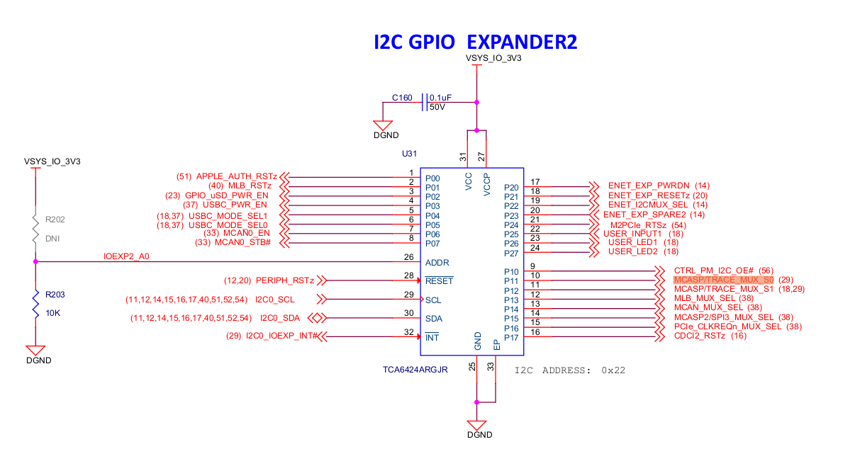
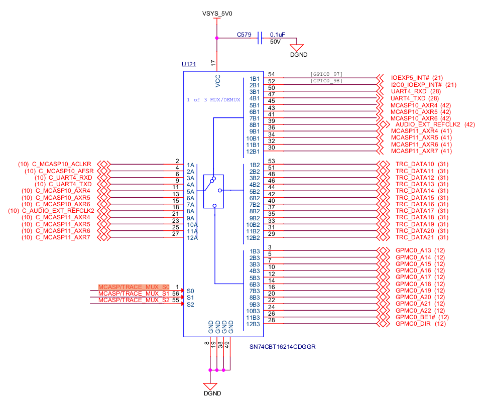
    Correct me if I am wrong.I was looking into the schematics and noticed that there is an extra mux in the path of main_uart4_txd/rxd. The selection pins of that mux can be controlled by an i2c GPIO expander. Since I do not need i2c driver in my system, I am not solely developing a driver for this until I am absolutely sure that this is the reason behind my main_uart4 not working. (see attached pics)

    Can anybody confirm this?

    Thanks
    Usman

  • Hi Usman,

       Your understanding is right. The mux is controlled by an I2c expander. However, the default settings are routed to use UART pins as shown in the diagram. You need not make any changes n I2C expander to get UART4 working.

    BTW, you can see here[0] on how gpio expander is programmed.

    [0] https://git.ti.com/cgit/ti-linux-kernel/ti-linux-kernel/tree/arch/arm64/boot/dts/ti/k3-j721e-common-proc-board.dts?h=ti-linux-5.4.y#n584

    Thanks and regards,

    Lokesh