Part Number: TMDSEVM6678
Tool/software: Code Composer Studio
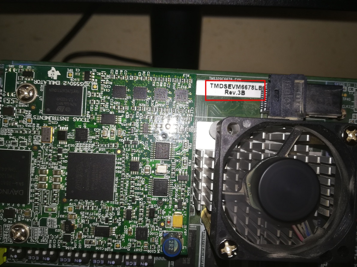
I have a TMDSEVM6678LE offering XDS560V2 debug probe via an mezzanine extension card; unfortunately it just broke and not working ....
I am wondering if the device has any other probe (eg. XDS100), and if yes how I would be able to get it to work.
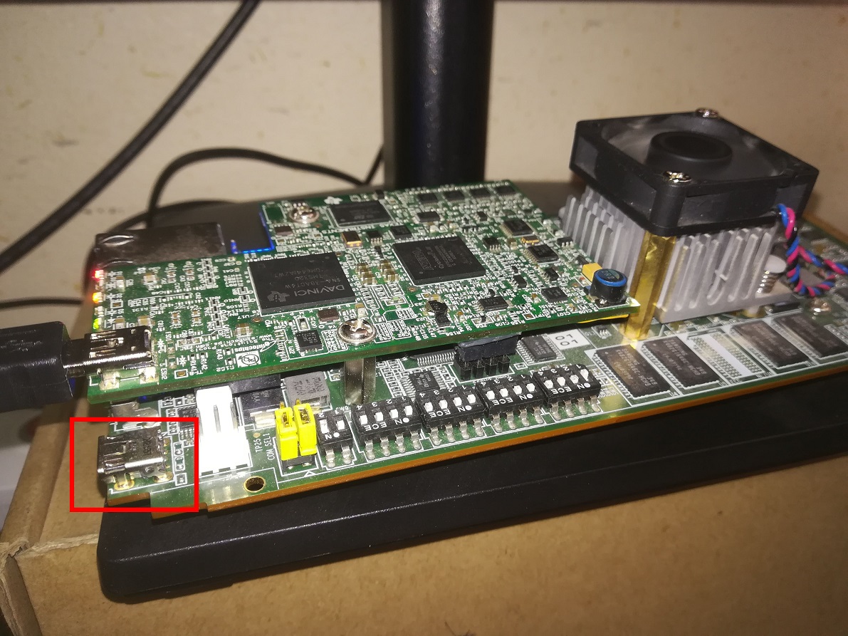
I could see another USB port on the main card and I am guessing it is XDS100 but I tried to test connection using three options as you can see below. However, none seems to be working; below I listed test logs for each of XDS100v1, XDS100v2, and XDS100v3. XDS100v2 complains the usb cable may be broken which might be true given it is 1 meter long.
Any advice is much appreciate it.

XDS100v1
[Start: Texas Instruments XDS100v1 USB Debug Probe_0]

Execute the command:

%ccs_base%/common/uscif/dbgjtag -f %boarddatafile% -rv -o -F inform,logfile=yes -S pathlength -S integrity

[Result]


-----[Print the board config pathname(s)]------------------------------------

C:\Users\MEHDI-~1\AppData\Local\TEXASI~1\
    CCS\ccs920\0\0\BrdDat\testBoard.dat

-----[Print the reset-command software log-file]-----------------------------

This utility has selected a 100- or 510-class product.
This utility will load the adapter 'jioserdesusb.dll'.
The library build date was 'Aug 26 2019'.
The library build time was '13:34:49'.
The library package version is '8.3.0.00003'.
The library component version is '35.35.0.0'.
The controller does not use a programmable FPGA.
The controller has a version number of '4' (0x00000004).
The controller has an insertion length of '0' (0x00000000).
This utility will attempt to reset the controller.
This utility has successfully reset the controller.

-----[Print the reset-command hardware log-file]-----------------------------

The scan-path will be reset by toggling the JTAG TRST signal.
The controller is the FTDI FT2232 with USB interface.
The link from controller to target is direct (without cable).
The software is configured for FTDI FT2232 features.
The controller cannot monitor the value on the EMU[0] pin.
The controller cannot monitor the value on the EMU[1] pin.
The controller cannot control the timing on output pins.
The controller cannot control the timing on input pins.
The scan-path link-delay has been set to exactly '0' (0x0000).

-----[The log-file for the JTAG TCLK output generated from the PLL]----------

There is no hardware for programming the JTAG TCLK frequency.

-----[Measure the source and frequency of the final JTAG TCLKR input]--------

There is no hardware for measuring the JTAG TCLK frequency.

-----[Perform the standard path-length test on the JTAG IR and DR]-----------

This path-length test uses blocks of 64 32-bit words.

The test for the JTAG IR instruction path-length failed.
The JTAG IR instruction scan-path is stuck-at-ones.

The test for the JTAG DR bypass path-length failed.
The JTAG DR bypass scan-path is stuck-at-ones.

-----[Perform the Integrity scan-test on the JTAG IR]------------------------

This test will use blocks of 64 32-bit words.
This test will be applied just once.

Do a test using 0xFFFFFFFF.
Scan tests: 1, skipped: 0, failed: 0
Do a test using 0x00000000.
Test 2 Word 0: scanned out 0x00000000 and scanned in 0xFFFFFFFF.
Test 2 Word 1: scanned out 0x00000000 and scanned in 0xFFFFFFFF.
Test 2 Word 2: scanned out 0x00000000 and scanned in 0xFFFFFFFF.
Test 2 Word 3: scanned out 0x00000000 and scanned in 0xFFFFFFFF.
Test 2 Word 4: scanned out 0x00000000 and scanned in 0xFFFFFFFF.
Test 2 Word 5: scanned out 0x00000000 and scanned in 0xFFFFFFFF.
Test 2 Word 6: scanned out 0x00000000 and scanned in 0xFFFFFFFF.
Test 2 Word 7: scanned out 0x00000000 and scanned in 0xFFFFFFFF.
The details of the first 8 errors have been provided.
The utility will now report only the count of failed tests.
Scan tests: 2, skipped: 0, failed: 1
Do a test using 0xFE03E0E2.
Scan tests: 3, skipped: 0, failed: 2
Do a test using 0x01FC1F1D.
Scan tests: 4, skipped: 0, failed: 3
Do a test using 0x5533CCAA.
Scan tests: 5, skipped: 0, failed: 4
Do a test using 0xAACC3355.
Scan tests: 6, skipped: 0, failed: 5
Some of the values were corrupted - 83.3 percent.

The JTAG IR Integrity scan-test has failed.

-----[Perform the Integrity scan-test on the JTAG DR]------------------------

This test will use blocks of 64 32-bit words.
This test will be applied just once.

Do a test using 0xFFFFFFFF.
Scan tests: 1, skipped: 0, failed: 0
Do a test using 0x00000000.
Test 2 Word 0: scanned out 0x00000000 and scanned in 0xFFFFFFFF.
Test 2 Word 1: scanned out 0x00000000 and scanned in 0xFFFFFFFF.
Test 2 Word 2: scanned out 0x00000000 and scanned in 0xFFFFFFFF.
Test 2 Word 3: scanned out 0x00000000 and scanned in 0xFFFFFFFF.
Test 2 Word 4: scanned out 0x00000000 and scanned in 0xFFFFFFFF.
Test 2 Word 5: scanned out 0x00000000 and scanned in 0xFFFFFFFF.
Test 2 Word 6: scanned out 0x00000000 and scanned in 0xFFFFFFFF.
Test 2 Word 7: scanned out 0x00000000 and scanned in 0xFFFFFFFF.
The details of the first 8 errors have been provided.
The utility will now report only the count of failed tests.
Scan tests: 2, skipped: 0, failed: 1
Do a test using 0xFE03E0E2.
Scan tests: 3, skipped: 0, failed: 2
Do a test using 0x01FC1F1D.
Scan tests: 4, skipped: 0, failed: 3
Do a test using 0x5533CCAA.
Scan tests: 5, skipped: 0, failed: 4
Do a test using 0xAACC3355.
Scan tests: 6, skipped: 0, failed: 5
Some of the values were corrupted - 83.3 percent.

The JTAG DR Integrity scan-test has failed.

[End: Texas Instruments XDS100v1 USB Debug Probe_0]
XDS100v2
[Start: Texas Instruments XDS100v2 USB Debug Probe_0]

Execute the command:

%ccs_base%/common/uscif/dbgjtag -f %boarddatafile% -rv -o -F inform,logfile=yes -S pathlength -S integrity

[Result]


-----[Print the board config pathname(s)]------------------------------------

C:\Users\MEHDI-~1\AppData\Local\TEXASI~1\
    CCS\ccs920\0\0\BrdDat\testBoard.dat

-----[Print the reset-command software log-file]-----------------------------

This utility has selected a 100- or 510-class product.
This utility will load the adapter 'jioserdesusb.dll'.
The library build date was 'Aug 26 2019'.
The library build time was '13:34:49'.
The library package version is '8.3.0.00003'.
The library component version is '35.35.0.0'.
The controller does not use a programmable FPGA.
The controller has a version number of '4' (0x00000004).
The controller has an insertion length of '0' (0x00000000).
This utility will attempt to reset the controller.
This utility has successfully reset the controller.

-----[Print the reset-command hardware log-file]-----------------------------

The scan-path will be reset by toggling the JTAG TRST signal.
The controller is the FTDI FT2232 with USB interface.
The link from controller to target is direct (without cable).
The software is configured for FTDI FT2232 features.
The controller cannot monitor the value on the EMU[0] pin.
The controller cannot monitor the value on the EMU[1] pin.
The controller cannot control the timing on output pins.
The controller cannot control the timing on input pins.
The scan-path link-delay has been set to exactly '0' (0x0000).

-----[The log-file for the JTAG TCLK output generated from the PLL]----------

There is no hardware for programming the JTAG TCLK frequency.

-----[Measure the source and frequency of the final JTAG TCLKR input]--------

There is no hardware for measuring the JTAG TCLK frequency.

-----[Perform the standard path-length test on the JTAG IR and DR]-----------

This path-length test uses blocks of 64 32-bit words.

The JTAG IR instruction path-length was not recorded.

-----[Perform the Integrity scan-test on the JTAG IR]------------------------

This test will use blocks of 64 32-bit words.
This test will be applied just once.

Do a test using 0xFFFFFFFF.
Scan tests: 1, skipped: 0, failed: 0

-----[An error has occurred and this utility has aborted]--------------------

This error is generated by TI's USCIF driver or utilities.

The value is '-183' (0xffffff49).
The title is 'SC_ERR_CTL_CBL_BREAK_FAR'.

The explanation is:
The controller has detected a cable break far-from itself.
The user must connect the cable/pod to the target.

[End: Texas Instruments XDS100v2 USB Debug Probe_0]
XDS100v3
[Start: Texas Instruments XDS100v3 USB Debug Probe_0]

Execute the command:

%ccs_base%/common/uscif/dbgjtag -f %boarddatafile% -rv -o -F inform,logfile=yes -S pathlength -S integrity

[Result]


-----[Print the board config pathname(s)]------------------------------------

C:\Users\MEHDI-~1\AppData\Local\TEXASI~1\
    CCS\ccs920\0\0\BrdDat\testBoard.dat

-----[Print the reset-command software log-file]-----------------------------

This utility has selected a 100- or 510-class product.
This utility will load the adapter 'jioserdesusbv3.dll'.

An error occurred while soft opening the controller.

-----[An error has occurred and this utility has aborted]--------------------

This error is generated by TI's USCIF driver or utilities.

The value is '-151' (0xffffff69).
The title is 'SC_ERR_FTDI_OPEN'.

The explanation is:
One of the FTDI driver functions used during the connect
returned bad status or an error. The cause may be one or
more of: no XDS100 is plugged in, invalid XDS100 serial number,
blank XDS100 EEPROM, missing FTDI drivers, faulty USB cable.
Use the xds100serial command-line utility in the 'common/uscif'
folder to verify the XDS100 can be located.

[End: Texas Instruments XDS100v3 USB Debug Probe_0]