This thread has been locked.

If you have a related question, please click the "Ask a related question" button in the top right corner. The newly created question will be automatically linked to this question.

PROCESSOR-SDK-AM335X: DMA programming

Part Number: PROCESSOR-SDK-AM335X


Hello,
I am trying to learn the DMA of the AM335x. I've been through the spruh73 reference manual, chapter 11, and as Jeffery Jones said in BeetleJuice "This thing reads like stereo instructions...".  So I've been through it several times.

So, fortunately, section 11.3.19 has some useful examples, and 11.5.3 has explicit steps to trigger a DMA transfer. So I am attempting to follow them explicitly. I have included that section for your reading pleasure.

DMA_spruh73q.pdf

My first attempt is something simple: Transfer a big block of memory (0x40000 bytes) from one place to another. All linear addressed. All blocks declared in global memory. Until I can make this work, trying to drive it from a peripheral would only complicate troubleshooting.

I have set it up to use queue 2, and the event is 12 (because it is defined as "open" in the doc) and the DCHMAP is set to a 1:1 assignment of the channel numbers to the maps).

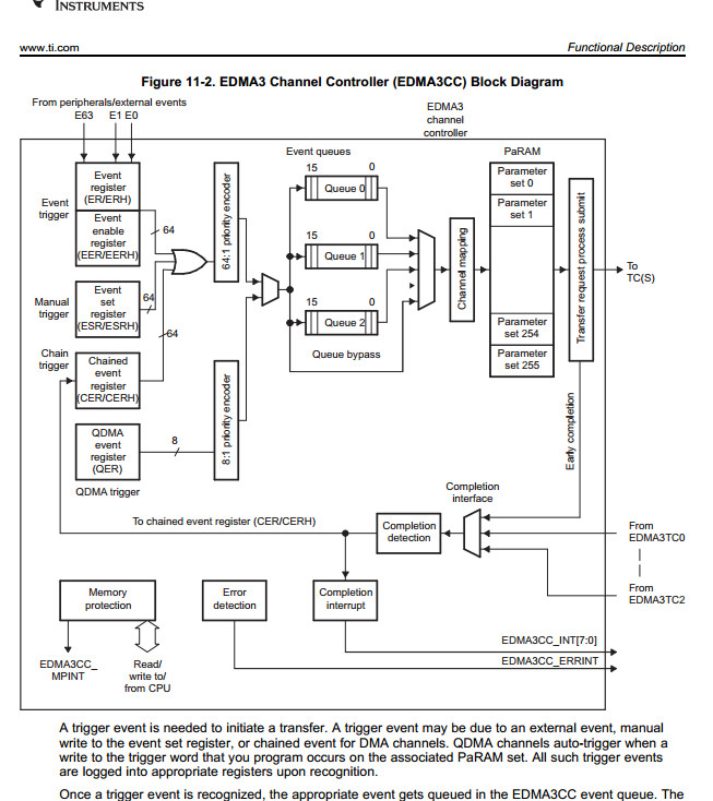
Question: What are any advantages to selecting which queue? And what is the setting to "bypass" a queue, as figure 11-2 shows in the reference manual?

The PaRAM is set to transfer 32767 for A-count, and 8 for B-count. The struct I used indicates that BIDX is a signed 16 bit number, so I kept it to only 15 bits, (0x7fff) in case for some reason, the register is actually using the sign bit.

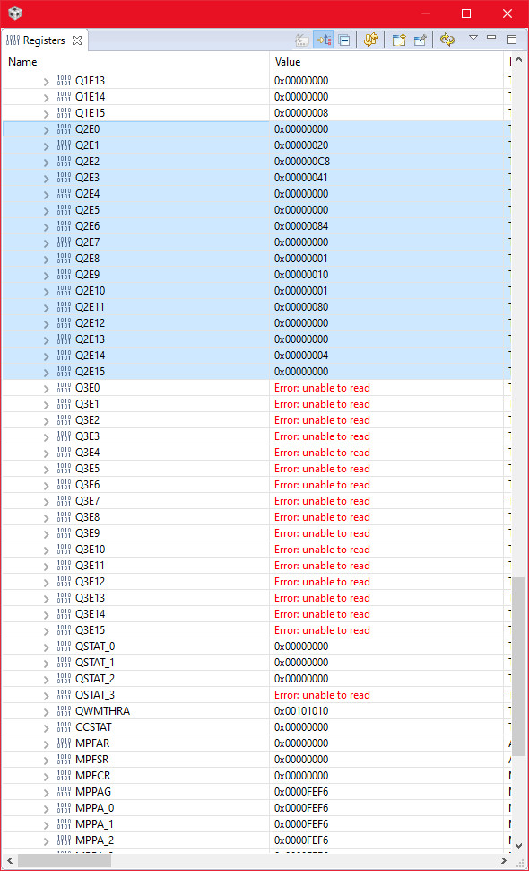
I have stepped through the code, and examined the registers, and verified that they appear to match the summary in section 11.5.3 (except where step 3.2 and step 3.2 are the exact same steps). I perform step 4.1.iii and wait to see what happens.

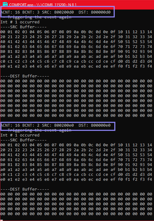
However, it is not working. The EDMA3CC_S_IPR register never set a bit to indicate that it completed. I also enabled the interrupts for all three possible events (complete, error, and mem protect error). Those interrupts never fire either. When I pause, or hit a breakpoint in the task (which is basically a sleep loop) the destination buffer is still empty.

I'm pasting the code of the code below. For the enjoyment of anyone who wishes look at it, I've included the entire CCS7 project.

It uses adaptations from StarterWare to program the registers, however, I have also included the necessary edma source files and headers. So the project essentially can stand on it's own. And I've scrubbed it for most of the superfluous or unused files.

/************************************
 * Looking for ANY interrupt event to see if the DMA tells us anything
 ****************************************/
void DmaComplete(unsigned int pValue) {  /* tpcc_int_pend_po0 */
    Hwi_clearInterrupt(12);
}

void DmaMemprotectErr(unsigned int pValue) {    /* tpcc_mpint_pend_po */
    Hwi_clearInterrupt(13);
}
void DmaError(unsigned int pValue) {    /* tpcc_errint_pend_po */
    Hwi_clearInterrupt(14);
}

Void DMATask(UArg a0, UArg a1) {
    unsigned int status;
    Hwi_Params edmaCompParams;              /* Int 12 */
    Hwi_Params edmaMemprotectErrParams;     /* Int 13 */
    Hwi_Params edmaErrorParams;             /* Int 14 */
    Error_Block eb;

    Hwi_Params_init(&edmaCompParams);
    edmaCompParams.priority = -1;
    edmaCompParams.maskSetting = Hwi_MaskingOption_SELF;
    edmaCompParams.enableInt = TRUE;
    Error_init(&eb);
    Hwi_create(12, DmaComplete, &edmaCompParams, &eb);

    Hwi_Params_init(&edmaMemprotectErrParams);
    edmaMemprotectErrParams.priority = -1;
    edmaMemprotectErrParams.maskSetting = Hwi_MaskingOption_SELF;
    edmaMemprotectErrParams.enableInt = TRUE;
    Error_init(&eb);
    Hwi_create(13, DmaMemprotectErr, &edmaMemprotectErrParams, &eb);

    Hwi_Params_init(&edmaErrorParams);
    edmaErrorParams.priority = -1;
    edmaErrorParams.maskSetting = Hwi_MaskingOption_SELF;
    edmaErrorParams.enableInt = TRUE;
    Error_init(&eb);
    Hwi_create(14, DmaError, &edmaErrorParams, &eb);

    Hwi_enableInterrupt(14);
    Hwi_enableInterrupt(13);
    Hwi_enableInterrupt(12);
    Hwi_enable();
    SetupEdma ();

    EDMA3SetEvt(SOC_EDMA30CC_0_REGS, EDMA3_MEMTSTEVT);
    Task_sleep(500);
    do {
        /*  Loop on complete of the IPR bits  (base plus 1068 for 1 = completed) */
        status = EDMA3GetIntrStatus(SOC_EDMA30CC_0_REGS);
        if (status != 0) {      /*  ANY int status every show up????   */
            UARTprintf("Int status is %04x\n",status);
            /*   Use ICR  (base + 1070) to clear  */
            EDMA3ClrIntr(SOC_EDMA30CC_0_REGS,EDMA3_MEMTSTEVT);
        }

        Task_sleep(50);
    } while (1);
}

void SetupEdma () {
    EDMA3CCPaRAMEntry paramSet;
    EDMAModuleClkConfig();
    /* This set a 1:1 mapping between the channel number and the PaRAM sets
     * Then sets ALL the registers to quenum, sets the global "regionID" to 0,
     * cleans up all the event flags */
    EDMA3Init(SOC_EDMA30CC_0_REGS, EVT_QUEUE_NUM);
    /*  Enable the EESR for event 12 */
    EDMA3EnableDmaEvt(SOC_EDMA30CC_0_REGS, EDMA3_MEMTSTEVT);

    /*  Enables the channel in the shadow region (is only 0 anyway)
     * yet another mapping of the channel to the queue number ( as did in "EDMA3Init)
     * Enable the event interrupt
     */
    /* Request DMA Channel and TCC */
    EDMA3RequestChannel(SOC_EDMA30CC_0_REGS, EDMA3_CHANNEL_TYPE_DMA,
                        EDMA3_MEMTSTEVT, EDMA3_MEMTSTEVT, EVT_QUEUE_NUM);

    /*  Now create the PaRAM settings  */
    /* Fill the PaRAM Set with transfer specific information */
    paramSet.srcAddr = (unsigned int) gSrcBuffer;
    paramSet.destAddr = (unsigned int) gDstBuffer;

   if ((paramSet.destAddr & 0x1F) != 0) {
       UARTprintf("Address Alignment Issue (not on 256 bit page)\n"); // For FIFO mode, destAddr must be a 256-bit aligned address. i.e. 5 LSBs should be 0.
       return;
   }

    paramSet.aCnt = 0x7fff;  /* 32767 bytes */
    paramSet.bCnt = 8;      /*  Do it in 8 blocks */
    paramSet.cCnt = 1;      /*  Total of 1 time */

    paramSet.srcBIdx = paramSet.aCnt;
    paramSet.destBIdx = paramSet.aCnt;

    paramSet.srcCIdx = 0;       /*  No jumps of the C index, because we don't */
    paramSet.destCIdx = 0;

    paramSet.linkAddr = 0xFFFF;   /* Address for linking (AutoReloading of a PaRAM Set) A value of 0xFFFF means no linking */
    paramSet.bCntReload = 0; // Only relevant for A-sync transfers (we are doing AB sync) ;
    /* OPT PaRAM Entries. */
    paramSet.opt = 0x00000000u;
    /* Source and Destination addressing modes are Incremental. */
    paramSet.opt |= EDMA3CC_OPT_DAM;  /*  Destination is "FiFo" with depth of 1 */
    paramSet.opt |= EDMA3CC_OPT_SAM;  /*  Destination is "FiFo" with depth of 1 */
    /* Setting the Transfer Complete Code(TCC). */
    paramSet.opt |= ((EDMA3_MEMTSTEVT << EDMA3CC_OPT_TCC_SHIFT) & EDMA3CC_OPT_TCC);
    /* Enabling the Completion Interrupt. */
    paramSet.opt |= EDMA3CC_OPT_TCINTEN;
    /* Transfer synchronization dimension. Specify AB-synchronized. Each event
     * triggers the transfer of BCNT arrays of ACNT bytes
     */
    paramSet.opt |= EDMA3CC_OPT_SYNCDIM;
    /* Now write the PaRAM Set */
    EDMA3SetPaRAM(SOC_EDMA30CC_0_REGS, EDMA3_MEMTSTEVT, &paramSet);
}

Any assistance on this would be appreciated. 

  • Update:

    It still doesn't work, but I found something.  Silly of me to assume that Line 5 in the original post,  Hwi_clearInterrupt(12) would actually clear the interrupt.  It's only in the function name.

    I updated the interrupt to this code, and added a global, which I could check in the mainline of the program.

    volatile unsigned int m_complete;
    void DmaComplete(unsigned int pValue) {  /* tpcc_int_pend_po0 */
        Hwi_clearInterrupt(12);
        EDMA3ClrIntr(SOC_EDMA30CC_0_REGS,EDMA3_MEMTSTEVT);
        m_complete++;
    }

    At least now the interrupt is only called once.

    I also turned off the SAM/DAM flags.  I don't know why I thought they needed to be on.

    Doing some debugging, I captured the PaRAM set for #12, and show in memory here  (address 0x4900 4180)

    I execute a single step triggering the event, and, as expected, the param set is now cleared.

    (except for the link, as one would expect)

    Next, it hits the interrupt breakpoint only once.  But the destination buffer is still not been updated.  Leaving the interrupt, and breaking on the mainline loop, the destination buffer is still not updated. 

    So now it is to the stage where it completes, and makes me believe the transfer has succeeded, but nothing has happened.  The interrupts for the errors never get triggered either, so there is no indication that there is any problem.

  • I have merge the minor changes based on the above information, and attached the current project.

    NOTE:  The doc says the PaRAM set is updated in "anticipation" of the next event being sent from the TC.  However the events and the interrupt are actually send from the TC.  And since the interrupt is being fired (and captured in a breakpoint) is it clear the TC has actually completed the request.

    But the buffer remains un-moved...

    2772.DMATest.zip

    Awaiting anyone advice...

  • Hi,

    Thanks for sharing the code. It will take me a bit of time to review the code and your findings. I'll get back with you in the next few days.

    Regards,
    Frank

  • Frank,

    Thanks for letting me know.

    Another easy question, also related to my trying to learn this:

    I have tried setting transfers to "AB" and to "A".   Still, there is no movement of the data from the source to the destination. But I can see the PaRAM block changing...  so that is teaching me something about the internals of the EDMA.

    Just for fun, I did this:  "A" count of 0x100, "B" count of 5, and "C" is 1.   I notice that "AB" does everything in one event as expected. And "A" only does the first array, and "B" decrements to 4.

    (Yes... This is expected, as I understand the doc.  But how do we continue from there?)

    The doc says this would take 5 events...  How are they re-fired?

    So I have to fire yet another "EDMA3SetEvt(...)"  to get it to move the next "A" array...   So how do know when to fire that event?

    •  I can fire it a bunch of times, and it all goes into the queue?  I would be limited to the queue size (of 16) assuming the source buffer is ready.
    •  I can poll for an intermediate event flag, and then issue it again?
    •  I can set the EDMA3CC_OPT_ITCINTEN intermediate interrupt, and then fire the next EDMA3SetEvt(..) from within the ISR?

    These seem "reasonable"...  And I suppose would depend on how the data is prepared into the source (or destination) from any peripheral.

    Are they the preferred ways to re-trigger events in a "A" transfer?

  • Frank, 

    One other thing related to DMA + SPI.  Not sure if we can continue it in this thread, or if I should start another.

    In the SPI module, shouldn't setting the DMAW flag cause the SPI module to generate the event in the EMDA?  I have the SPITX0 event bit set.  But the PaRAM is not decrementing.  It decrements once, and then just sits there.

    As my other reply indicates, I can see where my memory move might need to me manually triggered again, but the SPI module should be going those for me.

    I am not using the DAFTX register.  Just the normal TX0 register.  And when I enable the channel and the DMAW bit, the DMA PaRAM decremented once, so I looks like it tried to post the first byte.  But then nothing.

    (I've got it as a standalone project too, but first lets see what I'm not doing right in the first question.)

  • Frank...  Or anyone else who can shed some light on this.

    I have included the current test project.  It is still failing, I have been digging deeper.  Everything I see and read says it should be working.  BUT IT DOESN'T.

    I am attempting an "A" transfer with ACNT = 0x10 and BCNT = 0x10.  There should occur 16 "events" and it does (there are 16 interrupts that happen) 

    From the diagram in chapter 11, repeated below...  I set a manual trigger event.  It should:

    1. Go through the priority encoder (apparently it does)
    2. Go through queue 2  (registers say it's not, but the PaRAM is updated, so it must be... see later screen capture)
    3. Update the PaRAM (it does, see later screen capture)
    4. Notify the TC (I think it's TC2?  the registers for TC2 appear to have these counts and addresses in them)
    5. The TC2 then triggers an interrupt that it's done (It does)

    Wash, rinse, repeat,... the code captures the interrupt, and triggers the next transfer.  All this happens, but the destination memory is still not updated.

    How can the interrupt be triggered by the TC2 if the memory transfer didn't happen??

    Is there some issue with the DMA accessing DDR memory that would require L2/L3 flush?  (I doubt that, I also tried to transfer to a SPI TX register and hook in the SPI event, and that didn't work either)

    Here is the diagram from the doc.

    Here is a memory capture of PaRAM 12, at address 0x4900 4180 viewed during one of the breakpoints  It is clear that the BCNT value decrements from 0x010, and the src/dst addresses are being updated.

    Here is a shot of the registers.  The entries for Q2Ex all appear to have random stuff.  There is no queue containing the channel/event for the one I am using (event 12 or 0x0c).

    And the QSTAT_2 register STRPTR value never changes.  So, somehow the PaRAM is being updated while this event never gets through the queue...

    This is a screen capture of the console output, showing that the source buffer is NOT being moved to the destination.  But the PaRAMS are changing from one interrupt to another.

    I am now at a complete loss.  I have been through the doc repeatedly.  I have internalized the entire EDMA3 module to the point I could almost assemble it from memory.  Except if I did, mine would work.

    Is there any assistance available?

    Here is the entire project.

    6013.DMATest.zip

  • Hi,

    Sorry for the delayed response.

    I see you're using a mixture of your own code, CSL, Starterware and TI-RTOS.

    Please see this note in PRSDK docs: https://software-dl.ti.com/processor-sdk-rtos/esd/docs/06_03_00_106/AM335X/rtos/index_device_drv.html#csl

    The CSL component of AM335x/AM437x Processor SDK is referred as StarterWare in the legacy baseline releases. To maintain backward compatibility for existing applications on AM335x/AM437x SOCs, StarterWare low level package is retained. Customers are recommended to use driver interfaces for ease of migration of application software across SOCs.

    Hence I suggest using Starterware instead of CSL APIs. I also suggest using the EDMA3 Low-Level Driver instead of directly programming the EDMA using CSL or Starterware APIs.

    For details on the EDMA3 LLD, please see: https://software-dl.ti.com/processor-sdk-rtos/esd/docs/06_03_00_106/AM335X/rtos/index_device_drv.html#edma3

    Unfortunately I'm not able to locate any Starterware example for EDMA3 in the installed PRSDK content.

    There is a EDMA3 LLD memory-to-memory copy example here: edma3_lld_2_12_05_30E\examples\edma3_driver\src

    Details on building this example are here: https://e2e.ti.com/support/processors/f/791/t/916497

    I modified the instructions slightly to get the example to build for AM335x:

    subst R: c:\ti_am335x_06_03_00_106
    R:\pdk_am335x_1_0_17\packages\pdksetupenv.bat
    cd R:\edma3_lld_2_12_05_30E\packages
    set ROOTDIR= R:/edma3_lld_2_12_05_30E
    rename R:/edma3_lld_2_12_05_30E/packages/config.bld to R:/edma3_lld_2_12_05_30E/packages/_config.bld
    gmake PLATFORM=am335x-evm FORMAT=ELF examples

    I've attached my updated env.mak: 

    I see you're using your own MMU configuration code. Since this application uses RTOS, I suggest using the TI-RTOS MMU API.

    Have to checked whether this is related to cache coherency? I see the Starterware function CP15DCacheFlushBuff() commented out in your DMA ISR:

    volatile unsigned int m_complete;
    void DmaComplete(unsigned int pValue) { /* tpcc_int_pend_po0 */
    Hwi_clearInterrupt(12);
    EDMA3ClrIntr(SOC_EDMA30CC_0_REGS,EDMA3_MEMTSTEVT);
    
    // CP15DCacheFlushBuff((unsigned int) gDstBuffer, 512); <-- No affect
    m_complete++;
    }

    Since this application uses TI-RTOS, I suggest using the TI-RTOS Cache API.

    Regards,
    Frank

    https://e2e.ti.com/cfs-file/__key/communityserver-discussions-components-files/791/1108.env.mk

  • Frank,

    Our code base is very large, and simply replacing the starterware functions with the newer ones in the PDK would be a massive undertaking.  These the functions which are already in the project.

    In the case of all those functions, as well as modification to the MMU, they were brought into the source code tree so that they could be 'tweaked' where needed.  This was when the RTOS and BIOS were in their earlier stages, and lacking a lot of critical things we needed.

    The code which was imported is simply a collection of setting and reading registers directly.  Even now it is also more efficient and readable than tracing through the newer stuff.  Finally, they directly follow the reference manual, which is what I am trying to do.

    I tried using the CP15DCacheFlushBuff thinking there may be an issue with syncing the L2/L3/DRAM.  This function is simply a call to the ARM assembly instruction of have the CP15 do the flush.  However it had no effect.  I have no information about the RTOS Cache API, is there some  underlying assembly code which is different in order to accomplish the same goal?  

    I quick hand trace of the example you provide indicates that it is no different from what I am trying to do simply by reading the manual.  Except all the functions are opaque, behind the newer EDMA3 calls.  So I would have to reverse engineer all that code, in order to find out what it's doing that is beyond what the manual says.

  • It is fixed.

    For any one who comes across this, looking for an answer to a similar problem, here is is.

    There are two issues that have to be addressed, and they are both cache based.  To people such as myself (not intricately familiar with cache based architecture), it something to learn.

    Referencing the example code that was in my post:

    1.  The initial population of the source buffer 'gSrcBuffer' is occurring in the cache, but the DMA doesn't care.  It wants to use the DDR.  So the cache must be 'cleaned' (one might think it's "flushed" but that is incorrect in the ARM vernacular) which means telling the co-processor to resync the cache RAM with the DDR.  The function is inside the CP15.c module.  The call to is is the last line here:

        p = (unsigned char *) gSrcBuffer;  /*  Now...  Build the original buffer, set every  byte */
        for (x = 0; x < 512; x++) {
            *p = (unsigned char ) x;
            p++;
        }
        CP15DCacheCleanBuff((unsigned int)gSrcBuffer, sizeof(gSrcBuffer));

    The underlying function involves calling the assembler instruction "mcr" with the address of the cache row to clean in the register that is passed in, which is R1 in this fragment

        mcr p15, #0, r1, c7, c10, #1

    This needs to be called for every row (which varies by architecture, the AM335x appears to be 64 bytes per row). That takes care of insuring the memory in the DDR which the DMA system wants to use is sync-ed up with the cache. 

    2. Next, to use the destination memory, it is necessary to also tell the cache that the destination buffer is now invalid in cache.  They is done by setting the 'invalidate' flag, which will cause the co-processor to reload that cache line from DDR.  The code to do that is further down in the task which tracks when the interrupt occurs, specifically the function CP15DCacheFlushBuff(...).

            if (m_complete != lastcomplete) {
                UARTprintf("Int # %d occurred \n",m_complete);
                m_complete = lastcomplete;
                CP15DCacheFlushBuff(gDstBuffer, sizeof(gDstBuffer));
                DumpBuffer();
            }

    The underlying function involves calling the assembler instruction "mcr" with the address of the cache row to invalidate in the register that is passed in, which is R1 in this fragment

        mcr p15, #0, r1, c7, c6, #1

    Again, this needs to be called for every row.  By flagging the cache rows as invalid, the system will reload the cache from DDR.

    I obtained this information from the ARM System Developers Guide, by Andrew Sloss, Dominic Symes, & Chris Wright , ISBN 1-55860-874-0 chapter 12, and combined it with reading the CP15.c source module to determine the behavior of those functions.

  • Hi,

    I'm glad you were able to resolve the problem.

    Thanks very much for following up and posting the solution to the problem!

    Regards,
    Frank