This thread has been locked.

If you have a related question, please click the "Ask a related question" button in the top right corner. The newly created question will be automatically linked to this question.

AM6548: PCIe PTM local clock behaviour

Part Number: AM6548

Dear TI team,

I'm trying to synchronize our AM65x operating as an PCIe EP connected to a x86 processor via PCIe PTM.

Synchronizing the PTM local clock apparently "simply works" after enabling PTM in the PCIe register space, i.e. the PTM_REQ_CONTEXT_VALID register gets set, and I can see the PCIE_EP_PTM_REQ_LOCAL_LSB_OFF/...MSB_OFF being set to something that matches the current PTM time from the x86.

My issue is that I haven't yet found a reliable way of using the PTM local clock to synchronize other clocks within the AM65x from there. The main issue that I'm seeing is that the PTM clock update is not synchronized with CPTS module. IF the PTM local clock is not frequency adjusted to the PTM master, the PTM local clock is going to drift from the master clock. This means I'd have to make sure that the PTM local clock was recently updated, but for lower-order bits of PTM local clock it becomes difficult/impossible to tell what the PTM local clock time was that triggered a CPTS hardware push event. For higher-order bits of PTM local clock it's of course easier to tell what the PTM local clock time was at the time of the hardware push event, but the last PTM update could be seveal milliseconds old, and the clocks would have drifted.

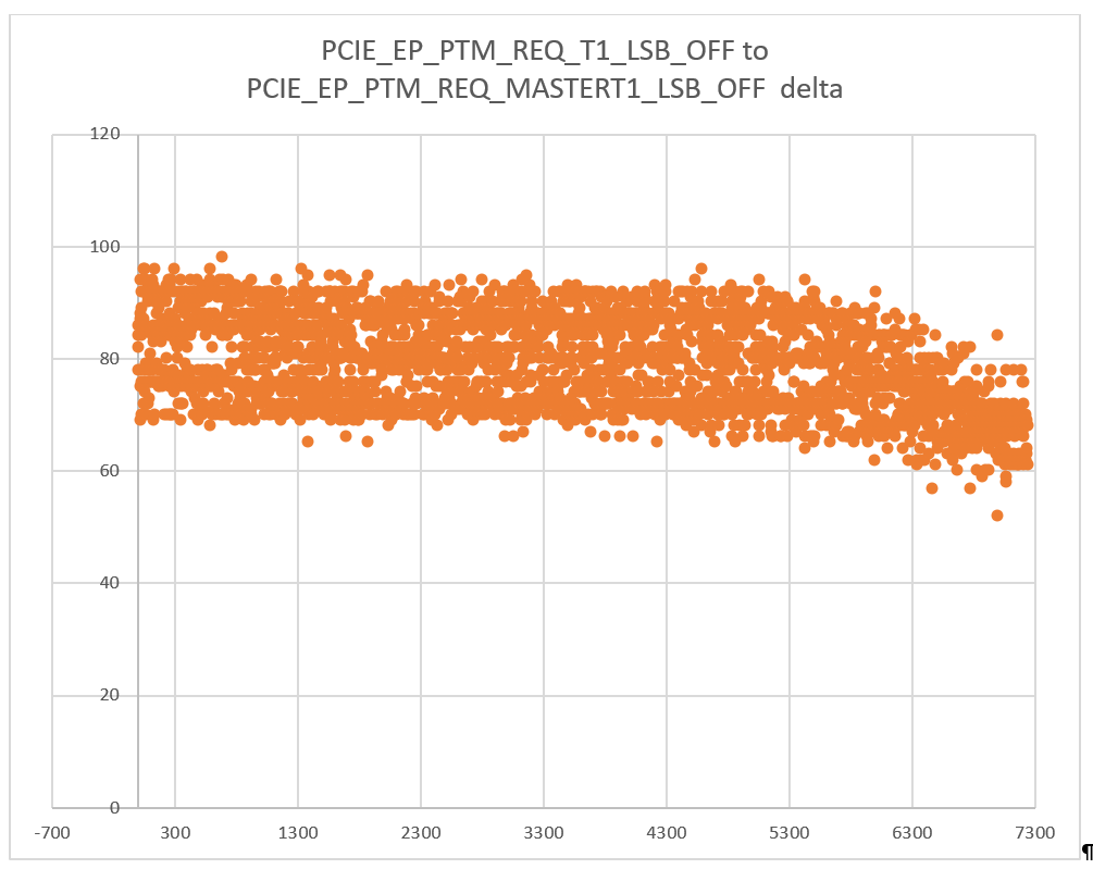
I'm assuming that the PTM local clock is not frequency adjusted to the synchronized master clock. In my current tests I'm seeing ~80ns difference between succsessive context updates (PTM_CLK_UPDATED interrupts) in the PCIE_EP_PTM_REQ_T1_LSB_OFF and PCIE_EP_PTM_REQ_MASTERT1_LSB_OFF registers.

  • Is it safe to assume that PCIE_EP_PTM_REQ_T1 vs. PCIE_EP_PTM_REQ_MASTERT1 shows the difference between PTM local clock and the PTM master clock at the time the PTM requester initiated the last update?
  • Is it safe to assume that PTM local clock got stepped to match the PTM master clock right before the PTM_CLK_UPDATED clock got signaled?
  • Is my assumption correct that the PTM local clock is not frequency adjusted to match the master clock?
  • Which clock signal is used to drive the PTM local clock?

Any guidance on how to use the PCIe PTM/CPTS functionality would be highly appreciated.

Regards,

Dominic

  • I'm trying to understand what options I have to make sure my HW TS push event is close to a previous PTM_CLK_UPDATED event.

    I believe that's the approach the TRM suggest, although I'm not sure how feasible that is:

    Software can enable the timestamp capture upon reception of the PTM Clock Updated interrupt.
    The PTM Clock Updated interrupt is asserted right after the EP has completed the PTM dialog with the
    RC and updated its local PTM timer. By using the interrupt to capture timestamps, software can ensure
    that the EP local time has been recently updated.

    What  happens when I set HW1_TS_PUSH_EN bit while the choosen PTM_LOCAL_CLOCK bit is already high? The TRM says that the HW push inputs are "Pulse" and need to stay asserted for at least 10 periods of the selected RCLK, but it doesn't contain a lot of details. Can I assume that "pulse" means "rising edge detection"? Is the edge detection already active while the *_TS_PUSH_EN bit is cleared, or is the hardware going to generate an event if I set the bit while the signal is already high?

    Regards,

    Dominic

  • Dominic, 

    I think the key confusion from you notes is that the PTM_LOCAL_CLOCK[63:0] is a continuous run, adjusted clock from the master clock. The 64-bit bus runs at 250MHz, so if there is no adjustment, the 64-bit bus will update every 4ns, with a increment of 4, as the timestamp are in 1ns units. The PTM core have build-in hardware state machine that calculates the different of the mastet and timestamps received from the RC side, then it adjusts the mast clock, and influence the ptm_local_clock output. 

    For example, if we configure the EP to initiate a PTM conversation every 10ms, then the ptm_local_clock will get a "boost" adjustment when it PTM recalculate, then it will keep this rate till next conversation/adjustment.  

    Directly reading received timestamps would require software implementation of the PTM calculation. you would have to read all timestamps received, then calculate path delays etc. 

    As you mentioned, the preferred method to use the PTM to sync other modules on the chip, is to use the HW1_TS_PUSH event, that is sourced from a selected bit of the ptm_local_clock. you can use it to calculate differences of RC clock and local clock, or directly use the PCIE local CPTS to nudge the GENF0 output, which can be routed to other peripherals on the chip as timer input. You may find some overview diagrams in the appnote at:

    https://www.ti.com/lit/pdf/spracp7

    regards

    Jian

  • I've checked the J721 TRM (SPUIL1A), and it seems to me that the PCIe<->CPTS integration was enhanced there to specifically solve the issue that I described above. On the J721e there's a PTM_LOCAL_TIMER_OUT_VALID signal that is connected to the HW1_TS_PUSH input instead of the PTM_LOCAL_CLOCK[0-63] mux, and a PCIE_USER_PTM_TIMER_LOW/HIGH register. I'm assuming (the description is unfortunately rather brief) that PCIE_USER_PTM_TIMER register is going to latch the PTM_LOCAL_CLOCK (the J721e doesn't use that term) right after it was updated (stepped?) to match the RC, and that this register is going to be valid until the next PTM dialog finished. That way I would have two timestamps, one in the PCIe/PTM domain and one in my local clock domain, and could calculate frequency and offset from there.

    Is there a chance that you could confirm that precise time synchronization via PCIe PTM is not possible with the AM65x, and that this was fixed in the J721e?

    Is there a chance that this was fixed in the AM65x SR 2.0, and just not yet documented?

    Is there a workaround to achieve precise time synchronization with the limited capabilities of the AM65x' PCIe<->CPTS integration?

    Regards,

    Dominic

  • Hello Jian,

    thanks for your reply, but that didn't answer my questions.

    Yes, I understand that the PTM_LOCAL_CLOCK is a continuous, adjusted clock from the master clock. My question was HOW that clock is adjusted, and how it behaves BETWEEN the 10ms updates. My assumption is that if the local clock (which clock signal is the source for that 250 MHz bus?) runs faster than the RC, then the PTM_LOCAL_CLOCK will be stepped backwards after the 10ms update, if my local clock runs slower than the RC, then PTM_LOCAL_CLOCK will be stepped forward. During the 10ms period the two clocks are going to drift away from each other.

    I've plotted the differences between PCIE_EP_PTM_REQ_T1_LSB_OFF and PCIE_EP_PTM_REQ_MASTERT1_LSB_OFF for several thousand PTM updates. Towards the end I cooled down the x86 using freeze spray:

    Without additional cooling the local T1 timestamp was consistently ~80ns ahead of the master T1. After applying the freeze spray the difference dropped significantly. To me that means that the x86 frequency increased slightly, and that the frequency of PTM_LOCAL_CLOCK is not adjusted to match the RC, but only stepped on every update.

    jian35385 said:

    For example, if we configure the EP to initiate a PTM conversation every 10ms, then the ptm_local_clock will get a "boost" adjustment when it PTM recalculate, then it will keep this rate till next conversation/adjustment.  

    Can you describe that "boost"? Is the PCIe core going to adjust the frequency with something like the PPM register of the CPTS, i.e. add/subtract an increment every N increments to increase or slow down the clock, or is it simply stepping the counter based on the latest calculation?

    jian35385 said:

    Directly reading received timestamps would require software implementation of the PTM calculation. you would have to read all timestamps received, then calculate path delays etc. 

    I was thinking of using the information from the received timestamps to calculate the frequency difference myself, to workaround the inability to properly synchronize the PTM_LOCAL_CLOCK and the CPTS clock. While I still think I might be able to compensate the frequency differences that way I don't think I would be able to properly synchronize the offset.

    Regards,

    Dominic

  • Dominic, 

    There are many points in your previous posts, I will try to answer some, then we can continue the iteration:

    >Is there a chance that you could confirm that precise time synchronization via PCIe PTM is not possible with the AM65x, and that this was fixed in the J721e?

    [Jian] You understanding is correct that if the RC clock changed dramatically within the 10ms PTM request interval, then the EP will be drifting away from RC until the next PTM conversation. This is true for either AM65 or other platforms. To capture such changes, shorter interval PTM conversations shall be programmed in EP. you can program the internal less than 1ms. 

    J721e uses a difference PCIe controller, that implemented PTM differently. Main difference is that the PTM core ONLY send out a snapshot of EP PTM timer, rather than a continuous clock. 

    >Is there a chance that this was fixed in the AM65x SR 2.0, and just not yet documented?

    [Jian] there is no change in PTM implementation in SR2.0, other than DMSG byte order issue.  Similar to any other protocols, time slave will be ticking at its most recent known rate, until the next sync. 

    >Is there a workaround to achieve precise time synchronization with the limited capabilities of the AM65x' PCIe<->CPTS integration?

    [Jian] lets align on first two questions then revisit the definition of "precise time sync". 

    A few other notes:

     - The 250 MHz bus frequency is sourced from the PCIe core. It is a fixed local clock. 

     - the PTM core (specific to M65xx, not in J7) has build in timers that sends out adjusted timestamp every 4ns, regardless there is a PTM conversation or not.

    Additionally, since you are testing with an x86 RC, please confirm you are using a PG2 silicon, as the bug in PG1 will trigger when connecting to a X86. 

    regards

    Jian

  • Hello Jian,

    thanks for your replies.

    jian35385 said:
    [Jian] You understanding is correct that if the RC clock changed dramatically within the 10ms PTM request interval, then the EP will be drifting away from RC until the next PTM conversation. This is true for either AM65 or other platforms.

    I'm not sure what you mean by "changed dramatically". The scenario I'm trying to resolve is a monotonically ticking RC to which I'd like to synchronize. If we assume a clock tolerance for the two systems of +-200ppm this would mean that the RC could increment for 10,002,000 ns within 10ms, whereas the EP might only increment for 9,998,000ns. That is unless there is some mechanism in place that adjusts the EP PTM local clock rate.

    jian35385 said:
    To capture such changes, shorter interval PTM conversations shall be programmed in EP. you can program the internal less than 1ms. 

    I thought of reducing the PTM dialog interval, too, but I'm seeing a few issues here:

    • The PTM interval would have to be very short to ensure the clocks don't drift too far apart. I'm not sure yet what kind of clock tolerance to expect, but PCIe for example requires +-300ppm. That means clocks could drift 600ns within 1ms.
    • You said "less than 1ms", but the PTM_REQ_LONG_TIMER is specified in ms. There is PTM_REQ_FAST_TIMERS but that is described as "Debug mode for PTM Timers". Do you any idea what the tradeoff with higher PTM dialog rates is?

    jian35385 said:
    J721e uses a difference PCIe controller, that implemented PTM differently. Main difference is that the PTM core ONLY send out a snapshot of EP PTM timer, rather than a continuous clock. 

    Yes, it only sends out that snapshot, but it is able to generate a CPTS HW TS push event at the same time. That way it is easy to correlate the last known good PTM time and one of the internal time bases. I guess we can use that as my definition of "precise" - timestamps from both time domains that are only affected by propagation delays, synchronization stages and so on.

    jian35385 said:
    [Jian] there is no change in PTM implementation in SR2.0, other than DMSG byte order issue.

    ...

    Additionally, since you are testing with an x86 RC, please confirm you are using a PG2 silicon, as the bug in PG1 will trigger when connecting to a X86.

    I saw that the TRM describesa new bit "PTM_REQ_PDEL_BYTE_REV" but unfortunately there is no issue documented in the errata for PG 1.0. I'm using PG 1.0 right now, but the PTM dialog itself appears to be working. Is the ReponseD message affected both as a sender (RC) and as a receiver (EP)? How does PG1.0 bug affect the PTM dialog?

    jian35385 said:
    Similar to any other protocols, time slave will be ticking at its most recent known rate, until the next sync. 

    Are you refering to the PTM local clock with "time slave"? In that case, what does "most recent known rate" mean? I'm always coming back to that question, which is already the title of this thread: How does the PTM local clock behave? Is it just monotonically increasing with "4ns" per 250 MHz cycle, or is it adjusted to match the last known rate from the RC? Is it stepped to match the RC on a successful PTM dialog?

    jian35385 said:
     - The 250 MHz bus frequency is sourced from the PCIe core. It is a fixed local clock. 

    Could you elaborate on that a bit more please? The whole PCIe/SerDes clocking is a bit unclear to me. We're using register settings based on the samples from the processor SDK, but I'm not sure if I fully understand these. Is that 250 MHz clock something generated from the PCIe RefClk pins, or is it internally generated? We program CTRLMMR_SERDES0_CTRL[1:0] to 0x1 (PCIe 0 lane 0), CTRLMMR_SERDES0_CTRL[7:4] to 0x4 (really not sure what that actually means) and CTRLMMR_SERDES0_REFCLK_SEL[1:0] to 0x3 for MAINHSDIV_CLKOUT4 (100 MHz).

    Is this 250 MHz clock generated based on the clock input via the RefClk pins, or is it generated based on the internally generated MAINHSDIV_CLKOUT4? As far as I understand this would be a key factor in determining how far the PTM local clock might drift from the RC PTM clock, right?

    jian35385 said:
     - the PTM core (specific to M65xx, not in J7) has build in timers that sends out adjusted timestamp every 4ns, regardless there is a PTM conversation or not.

    And again: HOW are these timestamps adjusted? Are they just compensating for the latest offset determined by the last PTM dialog, or are they adjusted to match the last known frequency of the RC?

    Making sure we get our system time synchronized as good as possible is a key factor for this project. It would be great if you could help us understand how to make the best out of the possibilities offered by the hardware.

    Regards,

    Dominic

  • Dominic, 
    please see some quick notes under each of the topics in discussion, I did get a chance to look up details in the TRM or errata, but can look up if there are discrepancies: 
    jian35385
    [Jian] You understanding is correct that if the RC clock changed dramatically within the 10ms PTM request interval, then the EP will be drifting away from RC until the next PTM conversation. This is true for either AM65 or other platforms.

    I'm not sure what you mean by "changed dramatically". The scenario I'm trying to resolve is a monotonically ticking RC to which I'd like to synchronize. If we assume a clock tolerance for the two systems of +-200ppm this would mean that the RC could increment for 10,002,000 ns within 10ms, whereas the EP might only increment for 9,998,000ns. That is unless there is some mechanism in place that adjusts the EP PTM local clock rate.

    [Jian] In this case, since the EP only knows the rate that that was last sync'ed, so he will not know the new ppm from RC until he initiate another PTM request. I think this is defined by the standard, as PTM conversations is only initiated by the EP as defined. Also note that in RC side, since typically the RC timestamps are derived from the REFCLK, it will follow the same requirement as PCIe for jitter requirements, not only tolerance. 

    jian35385
    To capture such changes, shorter interval PTM conversations shall be programmed in EP. you can program the internal less than 1ms. 

    I thought of reducing the PTM dialog interval, too, but I'm seeing a few issues here:

    • The PTM interval would have to be very short to ensure the clocks don't drift too far apart. I'm not sure yet what kind of clock tolerance to expect, but PCIe for example requires +-300ppm. That means clocks could drift 600ns within 1ms.
    • You said "less than 1ms", but the PTM_REQ_LONG_TIMER is specified in ms. There is PTM_REQ_FAST_TIMERS but that is described as "Debug mode for PTM Timers". Do you any idea what the tradeoff with higher PTM dialog rates is?

    [Jian] you may be right, i need to double check, but we rarely use less than 1ms due to overhead of sideband data and, again, system shall prevent/accommodate if the RC clock is fast changing (understand we still have different opinions on this tpoic)

    jian35385
    J721e uses a difference PCIe controller, that implemented PTM differently. Main difference is that the PTM core ONLY send out a snapshot of EP PTM timer, rather than a continuous clock. 

    Yes, it only sends out that snapshot, but it is able to generate a CPTS HW TS push event at the same time. That way it is easy to correlate the last known good PTM time and one of the internal time bases. I guess we can use that as my definition of "precise" - timestamps from both time domains that are only affected by propagation delays, synchronization stage[]s and so on.

    [Jian] yes, we implemented this way in J7. you will have trust software can read timestamps fast enough. Agree this allows processor cores in EP directly access the true timestamps send out by RC. 

    jian35385
    [Jian] there is no change in PTM implementation in SR2.0, other than DMSG byte order issue.

    ...

    Additionally, since you are testing with an x86 RC, please confirm you are using a PG2 silicon, as the bug in PG1 will trigger when connecting to a X86.

    I saw that the TRM describesa new bit "PTM_REQ_PDEL_BYTE_REV" but unfortunately there is no issue documented in the errata for PG 1.0. I'm using PG 1.0 right now, but the PTM dialog itself appears to be working. Is the ReponseD message affected both as a sender (RC) and as a receiver (EP)? How does PG1.0 bug affect the PTM dialog?

    [Jian] the delay sent back for X86 will be interpenetrated in reverse byte order. thus your PTM calculation will use a incorrect delay. of course if the X86 set the delay to 0, then no effect. Please check PG1 errata, there should be an errata. 

    jian35385
    Similar to any other protocols, time slave will be ticking at its most recent known rate, until the next sync. 

    Are you refering to the PTM local clock with "time slave"? In that case, what does "most recent known rate" mean? I'm always coming back to that question, which is already the title of this thread: How does the PTM local clock behave? Is it just monotonically increasing with "4ns" per 250 MHz cycle, or is it adjusted to match the last known rate from the RC? Is it stepped to match the RC on a successful PTM dialog?

    [Jian] I know this is where we deviates - lets try a few iterations to align. It is monotonic, and it is adjusting. that means you may see the same value put on the bus twice, but you will NOT see the stamp going backward - that will violates PTM protocol. As whether it is a step function, or spreaded adjustment like the CPTS does, I don't have the exact answer.  

    jian35385
     - The 250 MHz bus frequency is sourced from the PCIe core. It is a fixed local clock. 

    Could you elaborate on that a bit more please? The whole PCIe/SerDes clocking is a bit unclear to me. We're using register settings based on the samples from the processor SDK, but I'm not sure if I fully understand these. Is that 250 MHz clock something generated from the PCIe RefClk pins, or is it internally generated? We program CTRLMMR_SERDES0_CTRL[1:0] to 0x1 (PCIe 0 lane 0), CTRLMMR_SERDES0_CTRL[7:4] to 0x4 (really not sure what that actually means) and CTRLMMR_SERDES0_REFCLK_SEL[1:0] to 0x3 for MAINHSDIV_CLKOUT4 (100 MHz).

    Is this 250 MHz clock generated based on the clock input via the RefClk pins, or is it generated based on the internally generated MAINHSDIV_CLKOUT4? As far as I understand this would be a key factor in determining how far the PTM local clock might drift from the RC PTM clock, right?

    [Jian] TRM may not be clear enough on this - the 250MH clock is derived from the core clock that drive the PCIe controller core logic, it DOES NOT change or get adjusted. The REFCLK as mentioned, is the reference clock to the PCIe PHY, it is used by the PHY's internal CPU to generate the 8GHz bit clock, and it ALSO drives the byte clock interface where PHY connects to the controller. So far we are all talking about EP side, and nothing to do with RC or PTM. 

    jian35385
     - the PTM core (specific to M65xx, not in J7) has build in timers that sends out adjusted timestamp every 4ns, regardless there is a PTM conversation or not.

    And again: HOW are these timestamps adjusted? Are they just compensating for the latest offset determined by the last PTM dialog, or are they adjusted to match the last known frequency of the RC?

    [Jian] see above - PTM core have its own internal timers that adjusts. 

    Making sure we get our system time synchronized as good as possible is a key factor for this project. It would be great if you could help us understand how to make the best out of the possibilities offered by the hardware.

    [Jian] no problem on my side going by iterations, as this is how we can peel to the core of the doubts. 

    Regards,

    Dominic

  • Hello Jian,

    jian35385 said:
    [Jian] I know this is where we deviates - lets try a few iterations to align. It is monotonic, and it is adjusting. that means you may see the same value put on the bus twice, but you will NOT see the stamp going backward - that will violates PTM protocol. As whether it is a step function, or spreaded adjustment like the CPTS does, I don't have the exact answer.  

    Ok, I'm beginning to understand that you're trying to tell me that the EP's PTM local clock should be adjusted to match the most recent rate from the RC:

    • I couldn't find anything in the PTM specification (I'm looking at PCIe 3.1a chapter 6.22) that specifies the behavior of the requester. Could you quote the part where it says that the EP's PTM local clock must not be stepped backwards?
      • The spec does say that the PTM master time needs to be monotonic and strictly increasing, but nothing says that this extends to the EP's local clock (because it isn't part of the specification)

    The specification DOES say that "it is stronlgy recommended that an upstream port invalidate its internal PTM context when the relationship between PTM master time and the upstream port's local time changes, as determined by implementation specific criteria. An example for a change in the relation between PTM master time and upstream port's local time is accumulated PPM drift.

    • Can you tell me if the PTM requester implementation in the AM65x follows this recommendation, and what criteria it uses?

    • My experiments where I plotted T1 and T1-Master showed a pretty much constant difference, that was reduced by cooling down the x86. To me that indicates that the difference was determined by PPM drift, that got reduced because cooling down the x86 slightly increased it's rate.
    • I also saw an increased difference if I increased the PTM dialog interval. At the time I was looking at the PTM local clock in the EP config registers and at the RC's clock in the RC config registers separately, which is of course inaccurate, but the difference was pretty much linear with the increase of the PTM dialog interval.

    jian35385 said:
    As whether it is a step function, or spreaded adjustment like the CPTS does, I don't have the exact answer.

    This is crucial in my opinion. As long as we don't know how this clock behaves we don't know if we can reliably synchronize "anywhere" in the PTM dialog interval, or if we can only reliably synchronize somewhere close to a PTM local clock update. Is there any chance you could get that information, e.g. from Synopsys?

    IMHO stepping couldn't work at all, if what you say is true and the EP's PTM local clock is strictly increasing, too, because in that case "stepping" would mean to hold the time still for a prolonged period of time.

    jian35385 said:
    Please check PG1 errata, there should be an errata. 

    Unfortunately there is no such errata, at least not in the "SPRZ452E–July 2018–Revised June 2020".

    Regards,

    Dominic

  • Hello Jian,

    Dominic Rath said:
    I also saw an increased difference if I increased the PTM dialog interval. At the time I was looking at the PTM local clock in the EP config registers and at the RC's clock in the RC config registers separately, which is of course inaccurate, but the difference was pretty much linear with the increase of the PTM dialog interval.

    I've re-run my test with the increased PTM dialog interval. At the default PTM dialog interval of 10ms (PTM_REQ_LONG_TIMER=0x9) the difference between T1 and MASTERT1 is ~77ns. If I increase the PTM dialog interval to 100ms (PTM_REQ_LONG_TIMER=0x63), the difference between T1 and MASTERT1 is ~720ns. If I further increase the dialog interval to 200ms, the difference between T1 and MASTERT1 increases to ~1418ns.

    I'm looking at the following registers:

    PCIE_EP_PTM_REQ_T1_LSB/MSB_OFF: PTM Requester T1 Timestamp LSB/MSB

    PCIE_EP_PTM_REQ_MASTERT1_LSB/MSB_OFF: PTM Requester Master Time at T1 LSB

    To further verify this I've implemented a test that continously reads PCIE_EP_PTM_REQ_LOCAL_LSB/MSB_OFF and checks if the current value is greater or smaller than the previous value. Over a time of 10 seconds at a PTM dialog period of 256ms the PTM local clock was found to be stepped backwards 17 times. The test code read the PTM local clock ~20 million times, i.e. I'm sampling the PTM local clock every ~500ns.

    I'm pretty sure that the PTM requester local clock is NOT adjusted to match the master's frequency, but only stepped to the latest value determined by the PTM dialog.

    Regards,

    Dominic

  • Dominic, 

    I think we distilled your doubts to these questions:

    1. PTM core update - abrupt or gradual , can it step back?

    2. Are PCIE_EP_PTM_REQ_LOCAL_LSB/MSB_OFF true representation of the clk_out bus? can the register values step back

    3. CPTS HWPUSH event, can be level triggered or edge?

    I will chase down these questions and get back to you

    Jian

  • Dominic, 

    Please see below notes on the questions we discussed:

    1. PTM core update - abrupt or gradual , can it step back?

    2. Are PCIE_EP_PTM_REQ_LOCAL_LSB/MSB_OFF true representation of the clk_out bus? can the register values step back

    [Jian] I discussed with the IP owner and he believe the EP side may simply apply the adjustment based on PTM calculation to the PCIE_EP_PTM_REQ_LOCAL registers directly as a one-shot. Thus it can step back. I will check with the design files to confirm. 

    3. CPTS HWPUSH event, can be level triggered or edge?

    [Jian] The event must be edge triggered. This information is in the TRM Sec 11.1.3.9.4, where it also specified the pulse width need to be 10 clock cycles of the the RCLK. 

    regards

    Jian

  • Hello Jian,

    thanks for this feedback, and also thanks for the phone call.

    jian35385 said:
    [Jian] I discussed with the IP owner and he believe the EP side may simply apply the adjustment based on PTM calculation to the PCIE_EP_PTM_REQ_LOCAL registers directly as a one-shot. Thus it can step back. I will check with the design files to confirm. 

    Sorry if I keep pestering you about this, but the way you wrote your answer I'm still not sure what this means for us. We agreed in the phone call that the register interface is not going to be used for actual synchronization purposes. I've already proven that the register values can step backwards - the question is whether this "adjustment ... as one-shot" applies to the counter output via PTM_LOCAL_CLOCK as well.

    jian35385 said:
    [Jian] The event must be edge triggered. This information is in the TRM Sec 11.1.3.9.4, where it also specified the pulse width need to be 10 clock cycles of the the RCLK. 

    If the PTM_LOCAL_CLOCK[63:0] gets stepped forward or backward to account for clock drift between the RC and the EP, I believe the only option is the approach that I tried to outline in our phone call:

    • Wait for PTM clock updated interrupt
    • Enable the HW TS push
    • Wait for the CPTS event interrupt
    • Disable the HW TS push
    • using a PTM_LOCAL_CLOCK[n] bit that is sufficiently low-order so that a rising edge is "close" to the PTM clock updated interrupt

    Unfortunately from your answer I still don't know what is going to happen if I enable the HW TS push event (e.g. bit HW1_TS_PUSH_EN in PCIE_CPTS_CONTROL_REG) when the corresponding HW1_TS_PUSH signal is already high. This is a general CPTS question, and not limited to the PCIe PTM use case, since the same might happen if I use one of the externally accessible CPTS0_HW[12]TSPUSH signals.

    I believe the question is whether the HW<n>_TS_PUSH_EN bit is used to AND the HW<n>_TS_PUSH signal itself, or if it is used to AND the output of the edge detection logic:

    I understand that there's a race condition, i.e. if I look at the HW1_TS_PUSH signal BEFORE I set HW1_TS_PUSH_EN and find the signal low, and then look at the signal after setting the bit and find the signal high, then I wont know whether an event has been generated already, or if it is going to be generated on the next rising edge. But for all the other cases (low before and after, high before and after, high before and low after) I would know which edge triggered the event.

    Since you mentioned the "10 clocks" requirement from the TRM ("Each hardware time stamp input must be asserted for at least 10 periods of the selected RCLK clock."): Does that mean that the HW TS push has a fixed latency of 10 RCLK clocks? e.g. if I use a 100 MHz RCLK, is it guaranteed that the time stamp event is going to be generated at least 10 RCLK clocks after the rising edge of the HW<n>_TS_PUSH signal?

    Best Regards,

    Dominic

  • Dominic Rath said:

    Sorry if I keep pestering you about this, but the way you wrote your answer I'm still not sure what this means for us. We agreed in the phone call that the register interface is not going to be used for actual synchronization purposes. I've already proven that the register values can step backwards - the question is whether this "adjustment ... as one-shot" applies to the counter output via PTM_LOCAL_CLOCK as well.

    We've performed another test where we configured the PCIe CPTS to generate timestamps based on PTM_LOCAL_CLOCK bit 22 (toggles every ~4ms / ~8ms period). The EP PTM is synchronized to our RC with a PTM dialog period (PTM_REQ_LONG_TIMER) of 256ms. The timestamps captured by the CPTS are exactly 8388608ns (2^23) apart, except for every ~32nd timestamp that is ~2200ns later. This means that the PTM_LOCAL_CLOCK value that is output by the PCIe EP core ("clk_out bus") gets stepped backwards similar to the PCIE_EP_PTM_REQ_LOCAL_LSB/MSB_OFF registers on every PTM dialog (every 1...256ms).

    We've performed another test where we selected PTM_LOCAL_CLOCK bit 26 (toggles every ~67ms, i.e. stable for a long time), waited via polling for a high level on that bit, and then set then HW1_TS_PUSH_EN bit. The CPTS doesn't generate an event in that case, so I'm assuming that the workaround that I outlined is going to work.

    Regards,

    Dominic

  • jian35385 said:

    I saw that the TRM describesa new bit "PTM_REQ_PDEL_BYTE_REV" but unfortunately there is no issue documented in the errata for PG 1.0. I'm using PG 1.0 right now, but the PTM dialog itself appears to be working. Is the ReponseD message affected both as a sender (RC) and as a receiver (EP)? How does PG1.0 bug affect the PTM dialog?

    [Jian] the delay sent back for X86 will be interpenetrated in reverse byte order. thus your PTM calculation will use a incorrect delay. of course if the X86 set the delay to 0, then no effect. Please check PG1 errata, there should be an errata. 

    I believe I've already mentioned this during our conference call, but the errata (Rev. E) document doesn't mention this issue.

    I've got a setup with a PG2.0 AM65x, and our time synchronization fails unless I set the "PTM_REQ_PDEL_BYTE_REV" bit.

    If I look at the PCIE_EP_PTM_REQ_PROP_DELAY_OFF register I find values of 0x140 (+- a few digits) with PG 1.0 silicon or with PG 2.0 silicon and "PTM_REQ_PDEL_BYTE_REV" set. If I use PG 2.0 silicon and don't set the "PTM_REQ_PDEL_BYTE_REV" bit, the register reads "0x40010000", which is the erroneous value that I would have expected if there were a problem with the PG 1.0 silicon.

    With the bit set, the behaviour is identical to the PG1.0 hardware, i.e. the PTM_LOCAL_CLOCK drifts compared to the RC's clock (verified by looking at PCIE_EP_PTM_REQ_T1_LSB_OFF and PCIE_EP_PTM_REQ_MASTERT1_LSB_OFF).

    It looks like either the Apollo Lake x86 uses the same reversed byte order for the ReponseD message as the PG 1.0 AM65x, or there was no problem in the PG 1.0 implementation and PG 2.0 made it worse (but fixable, thanks to the "PTM_REQ_PDEL_BYTE_REV" bit).

    It would be great if you could confirm my findings.

    Regards,

    Dominic

  • Summary from offline discussion:

     Jian to:

    • send AM64 contact and check J7. 
    • share TI programming model of PTM
    • Align with Dominic on large-deviation situation 

    Jian

  • A follow-up email was sent to Dominic on:

    1. AM64 contact for PTM implementation

    2. J7 implementation

    3. TI method of PTM programming model on AM65. 

    Jian