This thread has been locked.

If you have a related question, please click the "Ask a related question" button in the top right corner. The newly created question will be automatically linked to this question.

TMDX654IDKEVM: SPi test header J20 chip select pin

Part Number: TMDX654IDKEVM

Hi there,

The following is true for our setup:

- Code Composer studio v9.1.0.00010
- PDK for AM65XX v1.0.5
- XDC tools v3.55.02.22
- IPC v3.50.03.05
- NDK v3.60.00.13

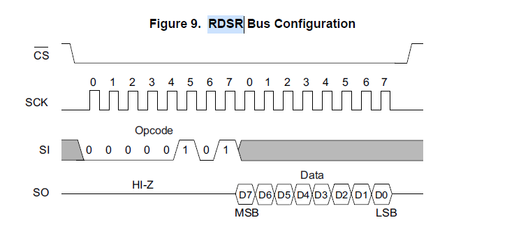
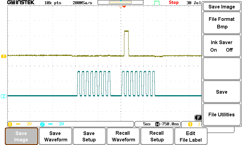
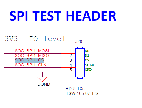
We want to test the SPI functionality with an external SPI device. According to my understanding, the chip select pin should be handled by the driver when calling SPI_transfer. Is this correct? This is done by defining the SPI_v1_HWAttrs.chNum field to 0 or 1, and that will correspond to chip select 0 and 1. When measuring the pins of the J20 test header, I can successfully measure the correct data being transmitted over the SCLK and D0 pins. However, nothing happens on the CS pin. Upon further investigation, this pin is connected directly to R317 and R316,l which is not placed on the board:

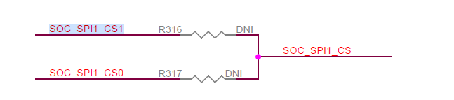
How will the chip select functionality work if there is no physical connection to the MPU? What do you suggest I do to be able to test the SPI functionality? Using a different pin as GPIO may work, however this is a bit disappointing that I should either solder a resistor in there, or use the GPIO module.

Kind regards

Johnny

  • Hi Johnny,

    SPI1_CS0 and SPI1_CS1 are connected to Display controller and HDMI controller respectively.

    You have to populate the resistors for CS to go to the test header.

    This is documented in IDK user guide under Ch 3.3.14.

    https://www.ti.com/lit/ug/spruim6/spruim6.pdf?ts=1596065930431&ref_url=https%253A%252F%252Fwww.ti.com%252Ftool%252FTMDX654IDKEVM

    Regards,
    Stanley

  • Hi Stanley,

    Thanks for your reply.

    I soldered a bridge onto R316 and I can see the CS1 signal on the test header switching successfully.

    I am however experiencing issues with receiving the correct data in my receive buffer of the SPI transaction. Please see below:

    1. I first set the SPI_v1_HWAttrs of SPI instance 1 as follow:

        SPI_socGetInitCfg(1, &spiCfg);
        spiCfg.baseAddr = CSL_MCSPI1_CFG_BASE;
        spiCfg.enableIntr = 0;
        spiCfg.chNum      = 1;
        SPI_socSetInitCfg(1, &spiCfg);

    2. I then call the SPI_Params_Init function and use the default parameters (SPI_POL0_PHA0 and 1Mhz clock) which is compatible with the external SPI device.

    3. I then open the SPI instance:

    hSpi1 = SPI_open(1, &spiParams);

    I now need to send the 0x05 byte over SPI to the external FRam device, which should return 1 byte as can be seen in the datasheet:

    I thus set up a SPI transaction as follow:

    uint8_t framRxBuf[100];
    uint8_t framTxBuf[100];
    uint32_t transferLength;
    
    while(1)
        {
    
            //To read status register
            framTxBuf[0] = RDSR; //0x05 = RDSR
            transferLength = 2;
    
            //Initialize the SPI transaction
            transaction.count = transferLength;
            transaction.txBuf = framTxBuf;
            transaction.rxBuf = framRxBuf;
    
            //Make the transaction, and store the reply that has been received in the framRxBuf
            SPI_transfer(hSpi1, &transaction);
    
            Task_sleep(1000);
        }

    I am expecting to receive the "0 1 0 0 0 0 0 0" in my receive buffer now. However, as can be seen in my receive buffer, the data received is all 0 (breakpoint at task_sleep):

    When I measure the data output pin of the external SPI device connected to the DI pin on the test header, I see the correct signal. The first 8 clocks is during the RDSR command, whereas the second 8 clocks is the data that is being sent out on the output line of the external SPI device. From the below measurement it is clear that the expected " 0 1 0 0 0 0 0 0" is in fact sent back to the EVM:


    Do you now what I am doing wrong in my software that I am not receiving the correct data that is actually being transmitted? What should the count member of the transaction be equal to? Should it include the size of the whole transaction (MOSI + MISO bytes) or only the MOSI bytes? I can also confirm that my hardware connection is correct. I tried changing the count size of the transaction, however that does nothing and only increases the amount of 0's I receive on the rxBuf.

    This leads me to think that either my SPI parameter settings is incorrect, hardware failure or just complete incorrect use of the SPI_transfer API.

    I look forward to hearing a reply soonest.

    Kind regards,

    Johnny Smith

  • Maybe just an update. When I port my source code into the example rtos application, my SPI transaction is working. There is thus some setting not set up correctly either in my .cfg, initmmu function or something.

    I commented out all other functionality in the actual application with only the SPI task running. This however does not work. I am continuing to investigate, but I will appreciate a reply in the meantime.

    Kind regards,

    Johnny Smith

  • In the example code, there is board init function being used to configure clock / pin mux / etc.

    Did you remove that from your own application?

  • The pin mux was not for my board. After changing the pin mux, receiving data works as expected.

    Thank you for your help.