Hi,
Hello, I am developing TDA4VM based on psdk_rtos_auto_j7_07_00_00_11. We use GPIO to enable the power supply of the camera module and deserializer.
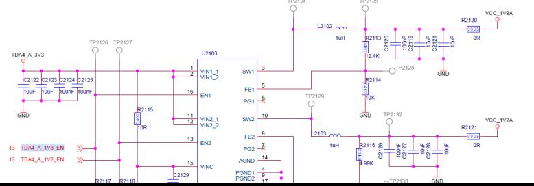
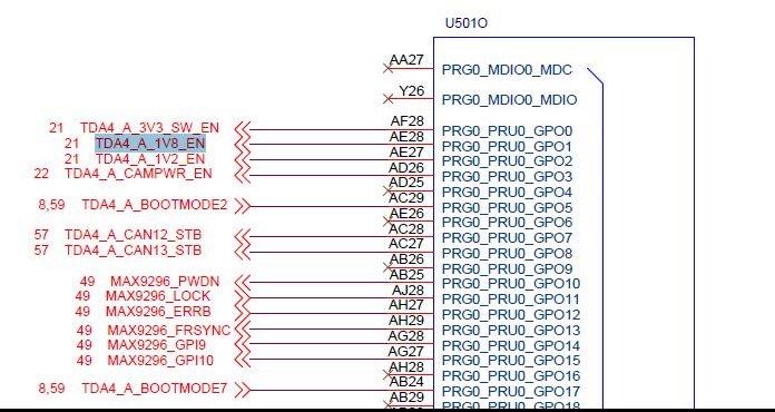
The schematic circuit diagram is as follows, I need to configure the AE28 pin to GPIO OUTPUT mode,
I modified the application program based on the code of psdk_rtos_auto_j7_07_00_00_11/vision_apps/basic_demo/app_single_cam;
1. In the app_single_cam.c file, add the following code in the vx_status app_create_graph(AppObj *obj) function:
uint16_t flag = 0x010f;
status = appWMBoardCameraPowerUp(flag);
2. Add the definition of appWMBoardCameraPowerUp function in the psdk_rtos_auto_j7_07_00_00_11/vision_apps/utils/iss/src/app_iss.c file:
int32_t appWMBoardCameraPowerUp(uint16_t power_up_flag)
{
    int32_t status = -1;

    appLogPrintf("enter appWMBoardCameraPowerUp !!!\n");

    memset(g_cmdPrm, 0, CMD_PARAM_SIZE);

    appLogPrintf("appWMBoardCameraPowerUp recv flag is 0x%x !!!\n", power_up_flag);
    if (((power_up_flag & 0xff00) >> 8) == 0x01)
    {
        g_cmdPrm[0] = 1;
    }
    else
    {
        g_cmdPrm[0] = 0;
    }

    g_cmdPrm[1] = power_up_flag & 0x0f;

    appLogPrintf("before IM_WM_CAMERA_POWER_UP cmd and cmd data[0] is 0x%x, data[1] is 0x%x!!!\n", g_cmdPrm[0], g_cmdPrm[1]);
    status = appRemoteServiceRun(
        APP_IPC_CPU_MCU2_0 ,
        IMAGE_SENSOR_REMOTE_SERVICE_NAME,
        IM_WM_CAMERA_POWER_UP,
        (void*)g_cmdPrm,
        2,
        0
    );

    return status;

}
3. Add the following code to the ImageSensor_RemoteServiceHandler function in the vision_apps/imaging/sensor_drv/src/iss_sensor.c file:
        case IM_WM_CAMERA_POWER_UP:

            power_on_7v_flag = *cmd_param;
            cmd_param++;
            camera_power_on_flag = *cmd_param;

            appLogPrintf("power_on_7v_flag is : %d, camera_power_on_flag is %d\n", power_on_7v_flag, camera_power_on_flag);
            if(power_on_7v_flag)
            {
                /***供7V电***/
                appLogPrintf("enableSenser7vpower\n");
                enableSenser7vpower();
            }

            if(camera_power_on_flag)
            {
                // enableSideCameraPower(camera_power_on_flag);
            }

            status = 0;
            break;
4. The enableSenser7vpower function in the vision_apps/imaging/sensor_drv/src/iss_sensor.c file is as follows:
void enableSenser7vpower(void)
{
    // Board_VM_CamPowerUp();

    int ret[2];

    WMBoard_GPIO(ret);
    appLogPrintf("WMBoard_GPIO ret[0] is %d, ret[1] is %d\n", ret[0], ret[1]);

}
5. Add in the pdk_jacinto_07_00_00/packages/ti/board/src/devices/common/common.c file
Board_STATUS WMBoard_GPIO(int *retStatus)
{

    Board_STATUS status = 0;
    int ret[2]

    BOARD_DEVICES_ERR_LOG("In WMBoard_GPIO function\n");

    Board_pinmuxUpdate(gCameraPowerPinmuxDataInfo,


    GPIO_v0_HwAttrs gpioCfg;
    ret[0] = GPIO_socGetInitCfg(0, &gpioCfg);
    gpioCfg.baseAddr = WM_BOARD_GPIO_BASE_ADDR;
    ret[1] = GPIO_socSetInitCfg(0, &gpioCfg);
    GPIO_init();
    /* Making Write protect line low to enable write access */
    GPIO_write(WM_BOARD_TDA4_A_1V8_EN_PIN_NUM, 1);

    *retStatus = ret[0];
    retStatus++;
    *retStatus = ret[1];

    return status;
}
6. Modify line132 line of pdk_jacinto_07_00_00/packages/ti/drv/gpio/gpio_component.mk
gpio_CORE_DEPENDENCY = yes
7. cd psdk_rtos_dir/vision_apps
make pdk
make imaging
It is ok
but when
make vision_apps
There has error info.
Below are my questions
1. In the app_tirtos project, I did not call the gpio port, why this error occurred? Any suggestions to solve the problem?
2. In the demo routine, I did not configure any pin mode, so how are the functions of each pin configured after the board is started? Now I need to modify the pin configuration, how should I modify it?
3. In the vision_app project, how should I use fast configuration and use gpio port?
Thanks
Kepei


