Part Number: TDA4VMXEVM
Other Parts Discussed in Thread: TDA4VM, USB2ANY
Dear experts,
I'm working on PSDKRA to build DSS examples and debug on J721E EVM target using CCS for debugging. I'm using the onboard XDS110 debugger.
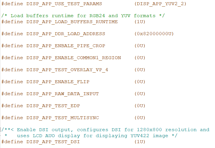
in pdk/packages/ti/drv/dss/examples/dss_display_test, I modifier the dss_display_test.h file in order to launch the test in DSI interface connected to HSD connector in the EVM. Here is the defined macros in this file:
There is also the file dss_display_dsi_cfg.c that must be updated, it contains the SerDes config. By default, it has this config:
uint8_t serdesConfig[][4] = {
{0x16, 0x01, 0x0A, 0x5},
{0x16, 0x03, 0x9A, 0x5},
{0x16, 0x17, 0x9E, 0x5},
{0x16, 0x07, 0x58, 0x5},
{0x16, 0x08, 0x22, 0x5},
{0x16, 0x70, 0x80, 0x5},
{0x16, 0x77, 0x24, 0x5},
{0x16, 0x01, 0x08, 0x5},
{0x16, 0x1E, 0x01, 0x5},
{0x16, 0x03, 0x9A, 0x5},
{0x16, 0x03, 0x9A, 0x5},
{0x16, 0x03, 0x9A, 0x5},
{0x16, 0x40, 0x04, 0x5},
{0x16, 0x40, 0x05, 0x5},
{0x16, 0x41, 0x21, 0x5},
{0x16, 0x42, 0x60, 0x5},
{0x16, 0x40, 0x09, 0x5},
{0x16, 0x40, 0x09, 0x5},
{0x16, 0x41, 0x21, 0x5},
{0x16, 0x42, 0x60, 0x5},
{0x16, 0x5b, 0x85, 0x5},
{0x16, 0x4f, 0x8c, 0x5},
{0x16, 0x4f, 0x84, 0x5},
{0x16, 0x40, 0x05, 0x5},
{0x16, 0x40, 0x04, 0x5},
{0x16, 0x41, 0x05, 0x5},
{0x16, 0x42, 0x16, 0x5},
{0x16, 0x40, 0x08, 0x5},
{0x16, 0x40, 0x08, 0x5},
{0x16, 0x41, 0x05, 0x5},
{0x16, 0x42, 0x0c, 0x5},
{0x16, 0x01, 0x00, 0x5},
{0x16, 0x66, 0x03, 0x5},
{0x16, 0x67, 0x03, 0x5},
{0x16, 0x65, 0x01, 0x5},
{0x16, 0x64, 0x00, 0x5},
{0x16, 0x64, 0x04, 0x5},
{0x27, 0x00, 0xFE, 0x5},
{0x11, 0x1D, 0x28, 0x5},
{0x11, 0x1D, 0x29, 0x5},
{0x11, 0x01, 0x06, 0x5},
{0x11, 0x01, 0x04, 0x5},
{0x11, 0x03, 0xf0, 0x5},
{0x11, 0x03, 0xf0, 0x5},
{0x11, 0x03, 0xf8, 0x5},
{0x11, 0x29, 0x00, 0x5},
{0x11, 0x29, 0x00, 0x5},
{0x11, 0x65, 0x00, 0x5},
{0x11, 0x65, 0x00, 0x5},
{0x12, 0x0C, 0x20, 0x5},
{0x12, 0x00, 0x01, 0x5},
{0x12, 0x04, 0xE6, 0x5},
};
My EVM is connected to UH948 deserializer through STP cable connected to HSD connector and then to a screen.
I tried with the config above but it's not working and this is normal since it's not the config of UH948 and the addresses 0x27 0x11 and 0x12 are not related to any client in my case.
Could you please provide me with the right configuration I have to use in this case where I use UH948 to the EVM?
Note: in the config above, the 0x16 is address of local serializer in the EVM, the UB941 but it has some error I think. Especially, the value written in register 0x5b, it must be 0x05 and not 0x85 bevause in this register we have to select Twisted-pair cable and not a Coax cable, the J721E evm has no coax cable interface, only for STP.
Another value I don't understand is last one written in register 0x64, it must be 0x5 and not 0x4, we have to enable pattern genertor.
Please make this issue clear for me.
Best reagrds,
Brahim