This thread has been locked.

If you have a related question, please click the "Ask a related question" button in the top right corner. The newly created question will be automatically linked to this question.

5509A Timer0 as ExtCLK Input Not Counting for Freq below 1MHz

I am using the 5509A and configuring Timer0 to be an external clock input.  I have used the CSL to set up the timer.

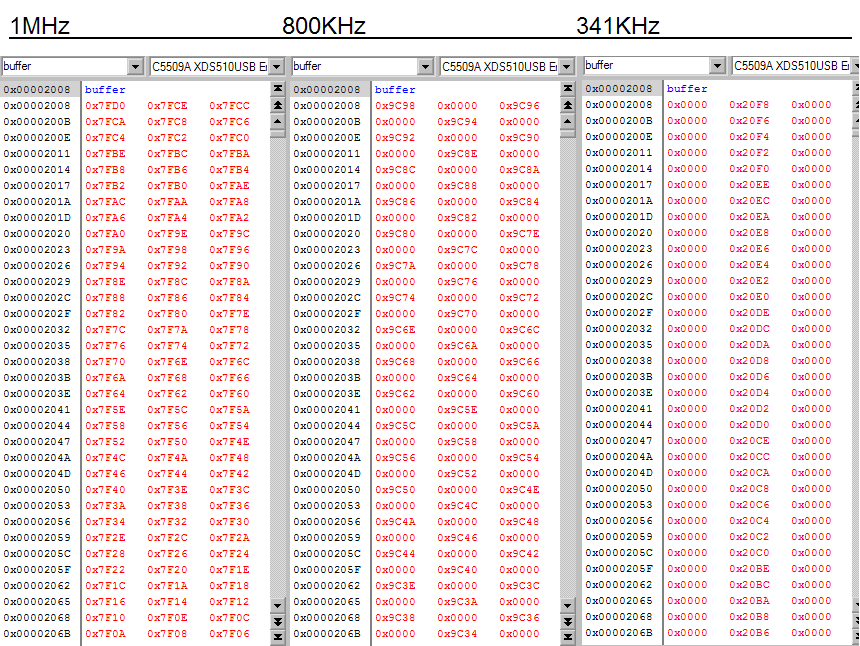
For frequencies above 1MHz, the TIM0 and PSC tick appropriately.  When the frequency is at about 1MHz or below, the TIM0 does not tick properly.  It appears to be ticking too fast; I assume it is a corruption of some sort.

The clock signal going in is very clean.

Any ideas?  I have improved the performance by inserting a delay between stopping the timer and reading the TIM0 and PSC values.

  • Some more information:

    It also seems that if we read the TIM0 register multiple times it alternates between zero and what we would consider to be the proper value.  This is also for frequency below 1MHz.

  • Upon further review:

    It seems that the act of stopping the timer and re-loading the TIM0 and PRSC0 registers caused the ERRTIM bit to be set only if the clock applied on the Tin/Tout pin (configured as Timer0 Running from an External Clock) had a frequency below 1MHz.  When the frequency was above 1MHz the error bit was not set.  Is there a restriction on the input clock speed?  The 5509A data sheet does not give a lower bound for input clock frequency.

    Is the reading of TIM0 dependent on the speed of the clock input to Timer0?  It seems that if the input to Timer0 is more than 1MHz, we CAN read TIM0 accurately after we stop the timer or while the timer is running.  If we read TIM0 while the clock input to Timer0 is below 1MHz, we notice a pattern.

    When we made consecutive reads of TIM0 in a loop:

    @ f = 800kHz  we get a proper value alternating with 0x0000.

    @ f = 100kHz we get a proper value every 10 readings, the rest filled with 0x0000.

    @ f = 50kHz we get a proper value every 20 readings, the rest filled with 0x0000.

    Is this pattern expected?  I can find no restrictions in the data sheet or the timers reference guide that mentions this.

    Any ideas?  We can work around this if the above behavior is guaranteed.

  • A little more information:

    When making multiple reads of the TIM0 register, as detailed above, the first reading was not always a proper value.  Sometimes it was 0x0000 and sometimes it was a proper count value.  Initially we thought that maybe the act of reading the register was making it inaccessible for a period of time, but it seems to give a proper value periodically without relation to our actions.

    Also, we have noticed if we do multiple reads with an accumulation between reads and with the accumulation removed, so that there is some time between reads with the accumulation code in and very little time between reads with the accumulation code out, we see the same ratio of proper values to 0x0000 values as detailed above.

    I will also add that we have constant activity on four DMA channels emptying and loading two McBSPs and a periodic external interrupt (every 256us).

  • Is your input clock sine wave or square wave?

  • The input clock is a 3.3V square wave.  It is generated by a CPLD.

  • It is interesting. I think we need to set up a bench to look into this issue. Please give us some time. I will see who can take a look at this issue and when we can set up a bench to test your issue.

  • Thank you, I will be interested to hear about your findings.

    For some further information, our intent is to use the Tin pin to detect and measure frequency.  We have periodic actions happening in our code and we'd like to be able to start Timer0 at a particular time and then stop Timer0 sometime later (on the order of 100ms) and then use the TIM0 and PRSC registers to count the periods.  We can derive a delta t (time change) using our existing processes  and calculate the frequency.

    The input signal is conditioned and buffered through a CPLD so that the output is a very clean square wave using 3.3V levels.

    Thanks for the help.

  • Mark Mckeown will take a look at this issue when he finishes the task he is working on. He may give you more questions once he starts looking at this.

    Regards,

    Peter Chung


  • Thanks Peter.  Standing by to stand by!

  • Hi,

    Sorry for the delay.

    I was able to reproduce your results on the C5509A with the Timer Running From an External Clock. See below.

    There does seem to be an interesting correlation between the period of the input signal and the number of zeros observed between each proper reading.

                Freq = 800kHz (T = 1.25 uS) --> proper value alternating with 0x0000
                Freq = 100kHz (T = 10 uS) --> proper value every 10 readings, the rest filled with 0x0000
                Freq = 50kHz  (T = 20 uS) --> proper value every 20 readings, the rest filled with 0x0000

    What is your DSP system clock speed?

    I will try to take a look at the RTL of the timer block to see exactly why this is happening and if the behavior is guaranteed.

    Best Regards,
    Mark

  • Mark,

    That is good to hear on our part.  Glad we are not going crazy.

    We are running our system at 200MHz from a 20MHz input to X2/CLKIN pin.  PLL is set to *30, /3 (PLL_CLKMD = 0x3F50).

    Thanks,

    Mark

  • Mark,

    Any word yet?  We'd like to have some input on the likelihood of this behavior being guaranteed.

    Thanks,

    Mark

  • Mark,

    Is there any word on this behavior?  We really need to know if the behavior we have discovered is guaranteed.  We are trying to move forward with our product design.

    Thanks,

    Mark

  • Mark Mckeown,

    Any word yet?  Have you been able to look at this issue, or is this something that has been pushed down the priority list?

    I'd like some feedback as we move forward with product developoment.

    Thank you,

    Mark

  • Hi Mark,

    I am very sorry that I have left you waiting this long without answers, but I have not been able to get my hands on the RTL as I had hoped...

    I can only reproduce the timer behavior that you see and postulate the cause of the behavior.

    The timer peripheral is being clocked externally, so I suspect that any register access to that peripheral will be allowed at the frequency of the external clock. Have you been able to scale the behavior by changing your system clock - i.e. keep the timer clkin signal stable at a frequency below 1MHz but slow down the system clock considerably to see if reading the timer registers returns 0x0000 values less frequently?

    Have you discovered any new behavior that may help the diagnosis?

    Are you able to move forward with this timer behavior and a workaround?

    Best Regards,
    Mark

  • Mark,

    Thanks for getting back to me.

    That is a good idea to slow down the system clock and see what changes.  We will have to give that a try when we get the chance.

    The good news is that the behavior we have seen seems to be completely stable.  Our workaround is to only use the timer when the CLKIN is above 1MHz.  We can deal with this and are fairly confident, but of course it would be great to have you guys be able to confirm that is expected behavior.

    I think that this is behavior that should definitely go into the documentation.

    Thanks for the help.  We will move forward with this.  I'd love to hear confirmation if you are able to look at the RTL.

    Cheers, 

    Mark

  • Mark,

    Glad to hear that you are moving forward.

    I will spend some more time with the C5509 in the near future as we begin supporting the C5509 eZdsp.

    If your issue comes up again and an explanation is found, I'll let you know.

    Cheers,
    Mark