This thread has been locked.

If you have a related question, please click the "Ask a related question" button in the top right corner. The newly created question will be automatically linked to this question.

Discrepancy in TC specs in the C6474 EDMA3 datasheet (SPRUG11A) and "C6474 Module Throughput" (SPRAAW5)

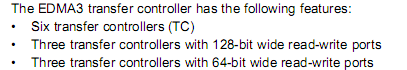
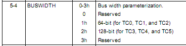
On page 68 of the manual in table 2-18 a listing is shown of the available TCs on the C6474 and according to the table they are all identical in specs. However, in SPRAAW5 (C6474 Module Throughput) on page 5, Figure 5, the EDMA TCs are split in 2 groups of 3: one group connected to the SCR A with a 128-bit wide bus and one group to SCR B with a 64-bit wide bus. On page 8, section 4.2 this is elaborated on.

My guess is that the "C6474 Module Throughput" document is correct, can somebody confirm?

Also, is the C6474 completely identical to the TCI6488? 

Thanks,

-Dirk


  • Dirk,

    It makes your job tougher to do when we drop these in consistencies in front of you. Sorry about that. SPRUG11a looks like a cut-and-paste issue; you can tell from the text line above Table 2-18 that there is something wrong at least with that sentence.

    Whenever there is doubt, you should consider the datasheet to be the primary authority. Not that it has never had errors, but we put more emphasis on it as the final document of what is in our chips. In this case, there are differences between all three, and with a bit of explanation the datasheet is correct.

    SPRUG11a Table 2-18 should have "8 bytes" on the BUSWIDTH line under TC3, TC4, and TC5.

    SPRAAW5 Figure 5 should have "x6" instead of  "x3" for the TCs on the top going to SCR-B, and the 64-bit bus width is correct.

    SPRS552g Figure 4-1 is correct with its bus widths and with the "x6" designations on both sets of TCs.

    We have discussed internally whether the "x3" or "x6" is more correct, and obviously the "x6" camp won. Each single TC has two independent VBUSM bus master ports, one for reads and one for writes. With multiple Transfer Requests (TR) "in-flight", it is possible and common for a single TC to simultaneously have read commands running on the read master port and also write commands running on the write master port. This can be a big throughput benefit for your system. And it means that each set of 3 TCs really has a total of six (6) master ports connected to its associated SCR. And the arrows always go Master to Slave even if the data moves the other way or not; the VBUSM commands go the direction of the arrow.

    No, the C6474 is not identical to the TCI6488. Support for TCIxxxx parts is not provided on the forum, or at least the experts for those markets do not monitor the forum but have their own direct support channels for the limited customers to whom TCIxxxx parts are marketed.

    Regards,
    RandyP


    If this does not answer your question, please tell us more. If it does, please click the  Verify Answer  button.

  • Thanks, I hadn't even noticed that sentence above Table 2-18. I think you made one typo though: 

    "SPRUG11a Table 2-18 should have "8 bytes" on the BUSWIDTH line under TC3, TC4, and TC5."

    Unless I am mistaken TC0, TC1 and TC2 are the transfer controllers which have 8 byte buses. After I looked more in SPRUG11a I found 2 more references to the TC databus width which do seem to be correct:

    In Chapter 1.2 Feature Summary:


    And also in chapter 4.3.2 EDMA3TC Configuration Register (TCCFG)


    I ran some speed tests with the LLD examples today and there is definitely a difference between TC0-TC2 and TC3-TC5. There's one thing I don't completely understand, although I am not sure how important it is: The "fast" TC3-5 are hooked up to SCRA. I was running some tests where I transfer 1MB of data from DDR to DDR in a single transfer. It is done 4 times in a row for every TC to get a good measurement. The setup is as follows (EVMC6474 rev D, CCSv3.3, cgtools v6.1.5, BIOS 5.41.10.36):

    - AB Sycnhronization

    - Self Chaining with a manual initial trigger and no intermediate interrupts

    - Normal completion (early completion does not give much of a difference here)

    - ACNT=16384, BCNT=1, CCNT=64

    On TC0-2 I get  ~846.1 MBps at best
    On TC3-5 I get  ~887.4 MBps at best

    I am using CSL_tscRead() to do measurements in combination with the transfer complete IRQ.


    The difference is about 5%, so not very much, but what I don't understand is why TC3-5 are faster in this case:

    According to Figure 4-1 of SPRS552g, the DDR controller is connected to SCRB (64-bit). For TC3-5 to get to the DDR controller, it has to go through Bridge 4 or/and (?) 5, which each constrict to 64 bit. I believe I read somewhere that the bridges themselves do some buffering, but I am still surprised that this route is faster than the one TC0-2 have to take.

    Thank you for your help. You already answered my original question, but this stuff is very interesting and keeps raising questions. 


    Regards,

    -Dirk


  • On page 4 of SPRAAW5 the DDR2 controller spec seems to be wrong as well:

    - 1.8-V, 32-bit DDR2 synchronous dynamic random access memory (SDRAM) external memory
    interface (EMIF) capable of 200-MHz (DDR2-400) to 400-MHz (DDR2-800) operation.

    The datasheet (SPRS552G) states:

    -16-/32-Bit DDR2-667 Memory Controller

    The EDMA3 throughput as measured on page 8 of SPRAAW5, Table 3 is for a 1GHz clock with 667MHz DDR2. What EDMA settings were used to measure this? A/B/C count, self chaining, early completion? When I do the same tests with a 1MB clock size (A/B/C counts = 16384 / 1 / 64) with early completion and self chaining, my measured values for L2-DDR are about 20% lower than the ones in SPRAAW5. Also, for my test-results, transfers using TC3-TC5 are about 6% slower than transfers using TC0-TC2. Maybe I'm doing something wrong, but I don't see what: In all other tests TC3-TC5  is faster than TC0-TC2.

    For L2-L2 measurements I get results about 8% lower. and for DDR - L2 measurements about 3% lower.

    I am using the LLD 1.10 examples and modified the first test to do the measurements.

    -Dirk