This thread has been locked.

If you have a related question, please click the "Ask a related question" button in the top right corner. The newly created question will be automatically linked to this question.

TDA4VM: How to enable MCAN interrupt on MCU2_0?

Part Number: TDA4VM

Hi,

The psdk version I use is psdk_rtos_auto_j7_07_00_00_11.

I wrote the MCAN0 test program according to the example of mcan_evm_loopback_app_main_k3.c, the baud rate is set to 500K, and I can currently receive the CAN data sent by the board on the PC.
But the problem is that my transmission does not start TX interrupt. The code to interrupt registration is as follows,

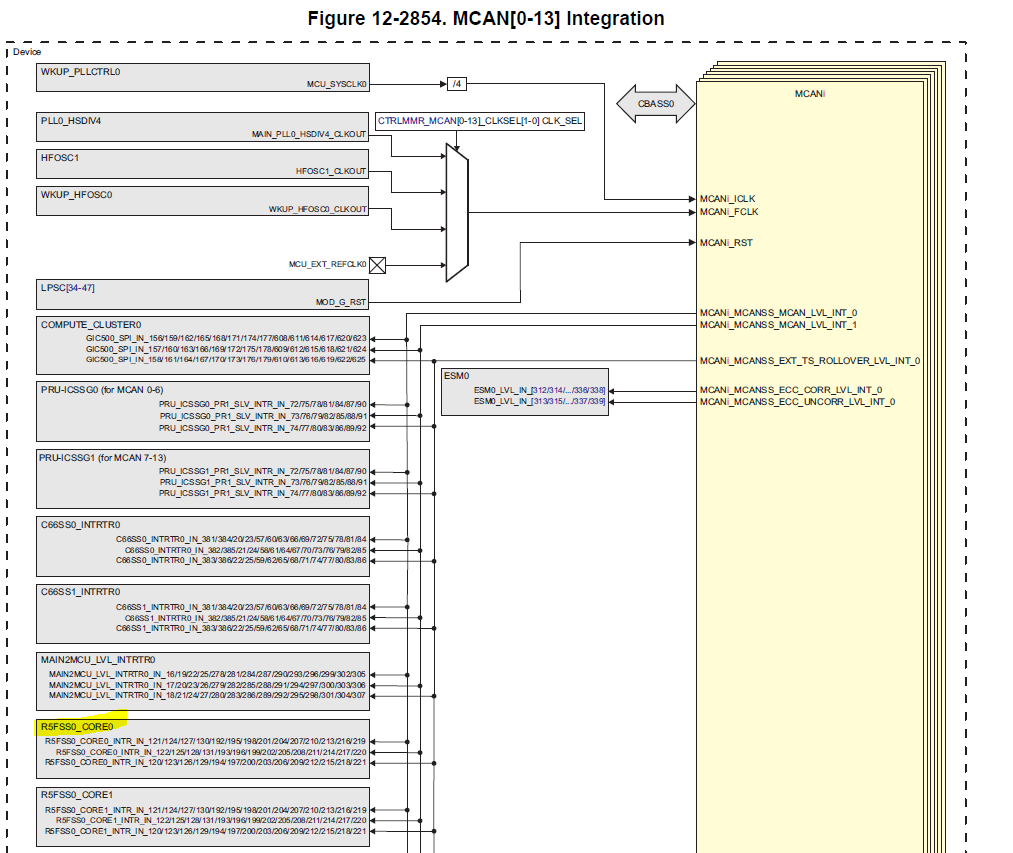
#define APP_MAIN_MCAN_0_INT0 (CSLR_R5FSS1_CORE0_INTR_MCAN0_MCANSS_MCAN_LVL_INT_0)
#define APP_MAIN_MCAN_0_INT1 (CSLR_R5FSS1_CORE0_INTR_MCAN0_MCANSS_MCAN_LVL_INT_1)
#define APP_MAIN_MCAN_0_TS_INT (CSLR_R5FSS1_CORE0_INTR_MCAN0_MCANSS_EXT_TS_ROLLOVER_LVL_INT_0)
static void McanIntr0ISR(uintptr_t arg)
{
uint32_t intrStatus;
VX_PRINT(VX_ZONE_ERROR, "INTERUPT");
intrStatus = MCAN_getIntrStatus(gMcanModAddr);
MCAN_clearIntrStatus(gMcanModAddr, intrStatus);
if (MCAN_INTR_SRC_TRANS_COMPLETE ==
(intrStatus & MCAN_INTR_SRC_TRANS_COMPLETE))
{
gMcanIsrIntr0Flag = 0U;
}

}
configStatus += App_mcanConfigureIrqRouter(TISCI_DEV_MCAN0, 0U, APP_MAIN_MCAN_0_INT0);
configStatus = App_mcanRegisterInterrupt(APP_MAIN_MCAN_0_INT0, &McanIntr0ISR);
configStatus += App_mcanRegisterInterrupt(APP_MAIN_MCAN_0_INT1, &McanIntr1ISR);
configStatus += App_mcanRegisterInterrupt(APP_MAIN_MCAN_0_TS_INT, &McanTSIntrISR);

The MCAN interface configuration code is as follows

boardCfg = BOARD_INIT_MODULE_CLOCK |
BOARD_INIT_PINMUX_CONFIG;

boardStatus = Board_init(boardCfg);
if (boardStatus != BOARD_SOK)
{
VX_PRINT(VX_ZONE_ERROR, "[Error] Board init failed!!\n");
}
configStatus = McanConfig();

/* Enable Interrupts */
MCAN_enableIntr(gMcanModAddr, MCAN_INTR_MASK_ALL, (uint32_t)TRUE);

MCAN_enableIntr(gMcanModAddr,MCAN_INTR_SRC_RES_ADDR_ACCESS, (uint32_t)FALSE);
/* Select Interrupt Line */
MCAN_selectIntrLine(gMcanModAddr,
MCAN_INTR_MASK_ALL,
MCAN_INTR_LINE_NUM_0);
/* Enable Interrupt Line */
MCAN_enableIntrLine(gMcanModAddr,
MCAN_INTR_LINE_NUM_0,
1U);

/* Enable Transmission interrupt */
configStatus = MCAN_txBufTransIntrEnable(gMcanModAddr,
1U,
(uint32_t)TRUE);
txMsg.dlc = loopCnt;

The can data sending code is as follows:

txMsg.id = (uint32_t)((uint32_t)(id) << 18U);
/* Write message to Msg RAM */
MCAN_writeMsgRam(gMcanModAddr, MCAN_MEM_TYPE_BUF, 1U, &txMsg);
/* Add request for transmission */
configStatus = MCAN_txBufAddReq(gMcanModAddr, 1U);
if (CSL_PASS != configStatus)
{
// App_ConsolePrintf("\nError in Adding Transmission Request...\n");
// break;
}

while (gMcanIsrIntr0Flag)
{}

Now we can correctly receive CAN data from the host computer, but the interrupt function McanIntr0ISR is not triggered.

1. Did we configure the interrupt number incorrectly?

2. Whether can provide correct MCAN interrupt configuration code, including TX and RX interrupt.

Thanks!

  • The following is the definition of App_mcanConfigureIrqRouter function:

    static int32_t App_mcanConfigureIrqRouter(uint32_t devId, uint32_t offset, uint32_t intNum)
    {
    int32_t retVal;
    struct tisci_msg_rm_irq_set_req rmIrqReq;
    struct tisci_msg_rm_irq_set_resp rmIrqResp;

    rmIrqReq.valid_params = TISCI_MSG_VALUE_RM_DST_ID_VALID;
    rmIrqReq.valid_params |= TISCI_MSG_VALUE_RM_DST_HOST_IRQ_VALID;
    rmIrqReq.src_id = devId;
    rmIrqReq.global_event = 0U;
    rmIrqReq.src_index = offset;
    rmIrqReq.dst_id = TISCI_DEV_R5FSS0_CORE0;
    rmIrqReq.dst_host_irq = intNum;
    rmIrqReq.ia_id = 0U;
    rmIrqReq.vint = 0U;
    rmIrqReq.vint_status_bit_index = 0U;
    rmIrqReq.secondary_host = TISCI_MSG_VALUE_RM_UNUSED_SECONDARY_HOST;
    retVal = Sciclient_rmIrqSet(&rmIrqReq, &rmIrqResp, SCICLIENT_SERVICE_WAIT_FOREVER);
    if(CSL_PASS != retVal)
    {
    VX_PRINT(VX_ZONE_ERROR,"Error in SciClient Interrupt Params Configuration!!!");
    VX_PRINT(VX_ZONE_ERROR,"offset: %d \n", offset);
    }
    else
    {
    VX_PRINT(VX_ZONE_ERROR,"SciClient Interrupt Params Configuration passed for offset: %d \n", offset);
    }
    return retVal;
    }

    The execution of this function will report an error message:

    Error in SciClient Interrupt Params Configuration!!!

  • Hi,

    To start with a few question:

    1. Is the use case where you want to use MAIN domain CAN namely MCAN0 and control it using the MCU2_0 (R5FSS0_CORE0)? Please confirm.
    2. If answer to 1 is yes then the MCAN0 interrupt to the MCU2_0 doesn't go through the interrupt router. (see below fig in TRM)

    1. Is there a reason why you want to control CAN from MCU2_0 instead of MCU2_1?

    Regards,

    Karan

  • Hi Karan,

    Thanks!

    1. Yes, We use MAIN domain CAN namely MCAN0 and control it using the MCU2_0 (R5FSS0_CORE0);

    2.Does "Is there a reason why you want to control CAN from MCU2_0 instead of MCU2_1" mean that I do not need to execute this line of code?

    configStatus += App_mcanConfigureIrqRouter(TISCI_DEV_MCAN0, 0U, APP_MAIN_MCAN_0_INT0);

    We encapsulated an openvx kernel. This kernel runs with MCU2_0. This is because there is no IPC of MCU2_1 on the psdk_rtos_auto_j7_07_00_00_11 version, so this kernel runs with MCU2_0.

    What is the difference between MCAN0 running on MCU2_0 and MCU2_1?

    Best regards!

    Kepei

  • Hi Karan,

    Sorry, There were some errors in the previous reply!

    1. Yes, We use MAIN domain CAN namely MCAN0 and control it using the MCU2_0 (R5FSS0_CORE0);

    2.Does "the MCAN0 interrupt to the MCU2_0 doesn't go through the interrupt router" mean that I do not need to execute this line of code?

    configStatus += App_mcanConfigureIrqRouter(TISCI_DEV_MCAN0, 0U, APP_MAIN_MCAN_0_INT0);

    We encapsulated an openvx kernel. This kernel runs with MCU2_0. This is because there is no IPC of MCU2_1 on the psdk_rtos_auto_j7_07_00_00_11 version, so this kernel runs with MCU2_0.

    What is the difference between MCAN0 running on MCU2_0 and MCU2_1?

    Best regards!

    Kepei

  • Hi Karan,

    Update my debugging status below.

    Today I debugged the receiving function, and the receiving interrupt can be triggered correctly. I removed this line of code.

     configStatus += App_mcanConfigureIrqRouter(TISCI_DEV_MCAN0, 0U, APP_MAIN_MCAN_0_INT0);

    But the sending interrupt is still unable to trigger

  • Hi Karan,

    Okay, this is weird.

    I removed a line of print statements in the sending interrupt, and now the sending interrupt is normal.

    Thank you for your help!

    Best regards!

    Kepei

  • Hi Kepei,

    buaawkp said:
    Does "the MCAN0 interrupt to the MCU2_0 doesn't go through the interrupt router" mean that I do not need to execute this line of code?

    Yes, and you figured it our correctly.

    buaawkp said:
    Does "the MCAN0 interrupt to the MCU2_0 doesn't go through the interrupt router" mean that I do not need to execute this line of code?

    I was saying this as the csl_mcan_evm_loopback_app which you took reference from was supported on mcu1_0 and mcu2_1. See psdk_rtos_auto_j7_06_02_00_21/pdk/packages/ti/csl/csl_component.mk

    csl_mcan_evm_loopback_app_$(SOC)_CORELIST = mcu1_0 mcu2_1

    Otherwise there is no HW restriction to control any CAN instance from any core.

    buaawkp said:
    I removed a line of print statements in the sending interrupt, and now the sending interrupt is normal.

    On this, even though it is working - what code did you have to change? Can you send me the source code highlighting the changes?

    Regards,

    Karan

  • Hi Karan,

    I added this line of printing code in the sending interrupt before.

    static void McanIntr0ISR(uintptr_t arg)
    {
    uint32_t intrStatus;
    VX_PRINT(VX_ZONE_ERROR, "INTERUPT");
    intrStatus = MCAN_getIntrStatus(gMcanModAddr);
    MCAN_clearIntrStatus(gMcanModAddr, intrStatus);
    if (MCAN_INTR_SRC_TRANS_COMPLETE ==
    (intrStatus & MCAN_INTR_SRC_TRANS_COMPLETE))
    {
    gMcanIsrIntr0Flag = 0U;
    }

    }
  • Hi Kepei,

    That would be a problem to have prints in the ISR. I would suggest if you need to count the number of interrupts then you add a global variable and increment it at the beginning (instead of the print)

    So something like:

    uint32_t intrCnt = 0;
    
    static void McanIntr0ISR(uintptr_t arg)
    {
        intrCnt++;
    
        ...
    }

    Regards,

    Karan

  • Hi Karan,

    Thank you for your good suggestions, I have solved the interruption problem.

    The new question is, I want to receive data with multiple IDs, such as 0x112~0x116, but the current acceptance filter only supports a single ID. How can I modify it?

    The filter settings are as follows:

    stdFiltelem.sfid2 = 0x0U;
    stdFiltelem.sfid1 = 0x6U;
    stdFiltelem.sfec = 0x7U;
    stdFiltelem.sft = 0x0U;

    The data read code is as follows:

    while (gMcanIsrIntrRxFlag)
    {}
    gMcanIsrIntrRxFlag = 1U;

    /* Checking for Errors */
    MCAN_getErrCounters(gMcanModAddr, &errCounter);
    if ((0U == errCounter.recErrCnt) &&
    (0U == errCounter.canErrLogCnt))
    {
    MCAN_getNewDataStatus(gMcanModAddr, &newDataStatus);
    MCAN_clearNewDataStatus(gMcanModAddr, &newDataStatus);
    MCAN_readMsgRam(gMcanModAddr,
    MCAN_MEM_TYPE_BUF,
    0U,
    0U,
    &rxMsg);

    }

    Regards,

    Kepei

  • Hi Kepei,

    Opened a new e2e (https://e2e.ti.com/support/processors/f/791/t/936434) to discuss this.

    Regards,

    Karan