This thread has been locked.

If you have a related question, please click the "Ask a related question" button in the top right corner. The newly created question will be automatically linked to this question.

AM5716: RSTOUTn

Part Number: AM5716
Other Parts Discussed in Thread: TMDXIDK5718

Hi,

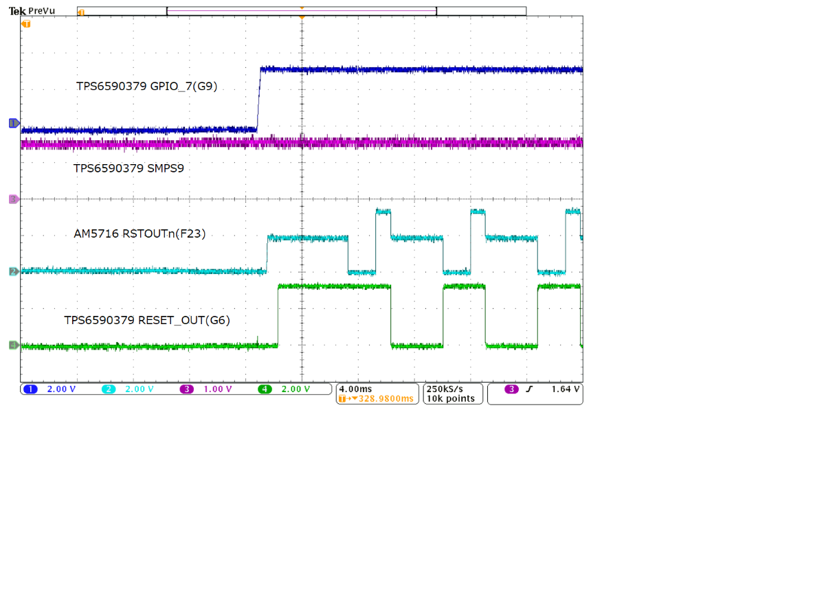
I am making a board similar to the MDXIDK5718 and checking the operation, but AM5716 and TPS6590379 reset alternately as shown in the attached figure, and AM5716 does not start.
Could you give me some advice as I do not know the cause? Also, is the assumed RSTOUTn waveform of AM5716 shown in the attached figure?
I've been asking a lot of questions on the power management forum, but I didn't find any issues with TPS6590379, so I'd like to know if there's anything wrong with AM5716.
Below is the URL.

e2e.ti.com/.../3473751

Thanks,

Keisuke

  • Hello,

    The rstoutn of the processor will be asserted if any hardware or software reset occurs.  Can you also show the waveform for the porz and resetn inputs to the SoC?

    Is the boot operation beginning prior to the 1st time the rstoutn is asserted?  Can you check that the boot interface is wiggling?  If boot is failing for whatever reason then software may reset the device via a software warm reset (which would also cause rstoutn to assert).

    Thanks,

    Kyle

  • Hi,

    The circuit I created is based on the basic evaluation board (TMDXIDK5718), and the TPS6590379 RESET_OUT (G6) in the attached photo and the AND of pushSW are input to Porz of AM5716.
    The resetn waveform cannot be taken immediately, but the resetn was constant at 3.3V.

    I'm not sure about the question you asked, so could you please tell me?

    Is the boot operation beginning prior to the 1st time the rstoutn is asserted?
    -Does this mean that the voltage from AM5716 pin number GPMC_AD0 / GPIO-GPMC_AD4 / GPIO rises correctly in the range from rtc_porz to rst_out as shown in Figure 5-2 of the data sheet?
    Like the evaluation board, the voltage source is supplied from SMPS9_SW of TPS6590379, so the voltage sequence is not adjusted here.

    Can you check that the boot interface is wiggling?
    -Which pin on AM5716 should I look at?

    Thanks,

    Keisuke

  • Keisuke,

    This will occur if you have a pullup on the AM57xx's RSTOUTn signal.  There is a note about this in the schematic checklist:

    If you are using the PMIC feature to workaround errata i862, make sure you do not have a
    pullup on RSTOUTn as it will cause an infinite reboot loop.

    The RSTOUTn signal is a push-pull signal, so you do not need a pullup on it like you would for an open drain output.  Once you remove the pullup this issue will be resolved.

    Best regards,
    Brad

  • Brad,

    Thank you for your reply.
    The board I made is similar to the evaluation board, with no pull-ups in the RSTout signal.
    I may be looking at it in the wrong place, so if it's on the evaluation board, could you please give me the reference number?
    Also, I think it would be quicker to talk about the circuit diagram I created, so I would like to send it.
    We have applied for request friendship, so please give us permission.
    Also, please answer the question I asked the other day.

    Best regards,
    Keisuke

  • Keisuke,

    I have seen this issue many times, and it is always due to a pullup on RSTOUTn.  Is there perhaps a device connected to RSTOUTn that has an internal pullup?  As a test, can you add an external pulldown somewhere on that net?

    Best regards,
    Brad


  • Brad,

    Thank you for your reply.
    Upon investigation, there was a pull-up on the DP83867 to which RSTOUT was connected. It was improved by putting a pull-down.
    Thank you very much.

    Best regards,
    Keisuke

  • Hi Keisuke,

    Thanks for the update and I'm glad you found the issue.  An external pulldown is the simplest/cheapest solution, but I wanted to offer one other possibility.  Another option to consider is to use an AND gate where RSTOUTn is one input, and a GPIO from the processor is the other input.  The output of the AND gate connects to reset of the PHY.  For the processor GPIO you need to either have an external pullup on the signal or choose one that has an internal pullup active by default.  The benefits of this approach are:

    1. Similar to your existing solution, on a power-up condition the PHY gets reset to make sure it's in a known good state.

    2. There's an additional benefit that you can reset the PHY under software control too.  This can be important in some circumstances.  Specifically, the DP83867 has 4-level bootstrap options.  The "high" and "low" levels are easy to achieve, but the mid-levels are pretty much impossible due to the internal pull in the processor.  By having the reset under software control you can first disable the internal pull in the AM57xx (e.g. on the RXD signals) such that you can attain a mid-level voltage when you take the PHY out of reset.

    Best regards,
    Brad