This thread has been locked.

If you have a related question, please click the "Ask a related question" button in the top right corner. The newly created question will be automatically linked to this question.

TDA4VM: USBn_VBUS condition

Part Number: TDA4VM

Hello,

I'm trying to operate the USB1 port as a device. 

I met a strange situation. USB0 and USB1 on my board have been operating with different VBUS voltage.

1) USB0 was recognized as a OTG-peripheral with 2V of VBUS.

2) USB1 was recognized as a peripheral with 3.2V of VBUS.

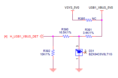
For the first time, both voltages of USB0_VBUS and USB1_VBUS were scaled down from 5V to 2V using the circuit in "7.3.3 USB VBUS Design Guidelines in the data sheet.

However, USB0 worked well, but USB1 got disconnected with 2V frequently about 200ms after the connection.

I changed a resistor and scaled up the voltage from 2V to 3.2V. It works well now.

I thought I had to change the voltage of VBUS_USB0 to the same voltage.

However, USB0 didn't go well with 3.2V.

I want to know the exact specification as follows for this problem.

1) The voltage range of VBUS for logic "1"

2) The voltage range of VBUS for connection or disconnection.

3) etc..

Thank you 

Regards,

Reuben

  • Reuben,

    What resistor values are you using?  The divider network shown in section 7.3.3 of the data manual, when implemented with the resistor values given, will cause the USBn_VBUS pin to detect connection for a (pre-division) VBUS value between 4.2V and 5.5V.  Your comment on "scaling down voltage from 5V to 2V" suggests different resistor values.

    On disconnect, could you look at the values in registers 0x6000014 and 0x6400014?  Please share both values after USB0 disconnect and after USB1 disconnect.

    -Zack

  • Hi, Zack

    Thank you for your reply.

    The divider network on my board is the same as the section 7.3.3. I attached a part of our schematic. You can see the same resistors and lines.

    I meant that this circuit reduced the voltage from 5v to 2v. 

    => 5V X (10K / (10K+16.5K+3.4K)) = 1.7V

    Technical Reference Manual says USB0_VBUS and USB1_VUBS pins are analog input and the input is 3.3V.

    I can't understand what 3.3v means. Is this max voltage? What voltage level is connection?

    We can't make any decision with this problem because we don't have enough information.

    Please give me some more specification of VBUS.

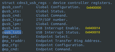
    Isn't 0x6400014 "USB Interrupt Enable register"? Don't you want to know "USB Interrupt Status register"(0x6400018)?

    I don't have the memory map for the register. I guessed them through the structure in gadget.h

    Thank you.

    Regards,

    Reuben.

  • 3.3V is the recommended max voltage for this pin.  I don't know what the exact threshold is for valid VBUS detection, however it is low enough that 4.2V or higher at the input of the divider network should be sufficient.

    I'm not sure how gadget.h is set up and how it translates to the USB registers.  However, the register at offset 0x14 contains status fields related to VBUS detection and OTG operation that could help us see what's going on.  According to the Main memory map in the TRM for this device, the base address are at 0x6000000 and 0x6400000:

    Could you provide a register dump of these memory ranges?  If not, just the registers I mentioned will be enough to get started.  I'd like to see it before and after connection with both voltage settigns (3.2V and 2V).

    -Zack