This thread has been locked.

If you have a related question, please click the "Ask a related question" button in the top right corner. The newly created question will be automatically linked to this question.

AM3352: rmii not working

Part Number: AM3352
Other Parts Discussed in Thread: DP83822I

Hi

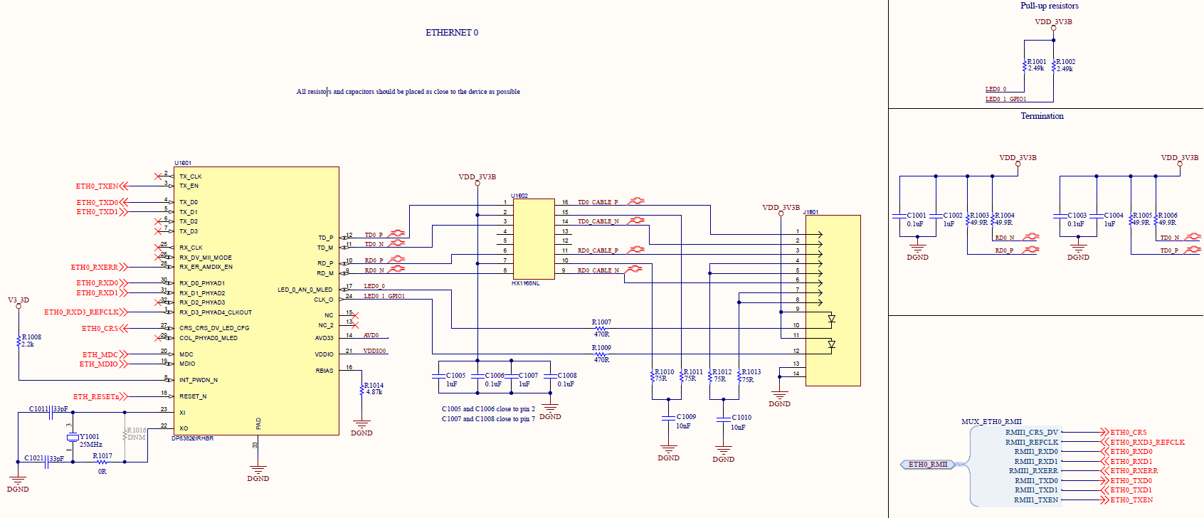
I've created a custom board, based on BeagleBone Black. I'm using am3352.

I have 1 Ethernet, just like BBB, but I'm using rmii instead of mii.

I've created the configuration according to this tutorial.

I have based the .dts and _defconfig files on BBB files

I've changed the mux.c and .dts files according to PINMUX TOOL:


mux.c

static struct module_pin_mux rmii1_pin_mux[] = {
        {OFFSET(mdio_clk), MODE(0) | PULLUP_EN},        /* MDIO_CLK */
        {OFFSET(mdio_data), MODE(0) | RXACTIVE | PULLUP_EN}, /* MDIO_DATA */
        {OFFSET(mii1_crs), MODE(3) | RXACTIVE},         /* MII1_CRS */
        {OFFSET(mii1_rxerr), MODE(3) | RXACTIVE},       /* MII1_RXERR */
        {OFFSET(mii1_txen), MODE(3)},                   /* MII1_TXEN */
        {OFFSET(mii1_txd1), MODE(3)},                   /* MII1_TXD1 */
        {OFFSET(mii1_txd0), MODE(3)},                   /* MII1_TXD0 */
        {OFFSET(mii1_rxd1), MODE(3) | RXACTIVE},        /* MII1_RXD1 */
        {OFFSET(mii1_rxd0), MODE(3) | RXACTIVE},        /* MII1_RXD0 */
        {OFFSET(rmii1_refclk), MODE(1) | RXACTIVE},     /* RMII1_REFCLK */
        {-1},
};


.dts

cpsw_default: cpsw_default {
                pinctrl-single,pins = <
                        /* Slave 1 */
                        AM33XX_IOPAD(0x90c, PIN_INPUT_PULLUP | MUX_MODE1) /* (H17) gmii1_crs.rmii1_crs_dv */
                        AM33XX_IOPAD(0x910, PIN_INPUT_PULLUP | MUX_MODE1) /* (J15) gmii1_rxer.rmii1_rxer */
                        AM33XX_IOPAD(0x914, PIN_OUTPUT_PULLDOWN | MUX_MODE1) /* (J16) gmii1_txen.rmii1_txen */
                        AM33XX_IOPAD(0x928, PIN_OUTPUT_PULLDOWN | MUX_MODE1) /* (K17) gmii1_txd0.rmii1_txd0 */
                        AM33XX_IOPAD(0x924, PIN_OUTPUT_PULLDOWN | MUX_MODE1) /* (K16) gmii1_txd1.rmii1_txd1 */
                        AM33XX_IOPAD(0x940, PIN_INPUT_PULLUP | MUX_MODE1) /* (M16) gmii1_rxd0.rmii1_rxd0 */
                        AM33XX_IOPAD(0x93c, PIN_INPUT_PULLUP | MUX_MODE1) /* (L15) gmii1_rxd1.rmii1_rxd1 */
                        AM33XX_IOPAD(0x944, PIN_INPUT_PULLUP | MUX_MODE0) /* (H18) rmii1_refclk.rmii1_refclk */
                >;
        };


I'm using DP83822I, and refering to this documentation link, I've changed the 0x17 register to "enable RMII mode of operation".

The u-boot is recognizing the device

=> mii device 
MII devices: 'ethernet@4a100000' 
Current device: 'ethernet@4a100000'
=> mii info 1 
PHY 0x01: OUI = 0x80028, Model = 0x24, Rev = 0x00, 100baseT, FDX
=> mii read 1 0x17
0065
=> mii dump 1 0
0.     (3100)                 -- PHY control register --
  (8000:0000) 0.15    =     0    reset
  (4000:0000) 0.14    =     0    loopback
  (2040:2000) 0. 6,13 =   b01    speed selection = 100 Mbps
  (1000:1000) 0.12    =     1    A/N enable
  (0800:0000) 0.11    =     0    power-down
  (0400:0000) 0.10    =     0    isolate
  (0200:0000) 0. 9    =     0    restart A/N
  (0100:0100) 0. 8    =     1    duplex = full
  (0080:0000) 0. 7    =     0    collision test enable
  (003f:0000) 0. 5- 0 =     0    (reserved)


=> mii dump 1 1
1.     (786d)                 -- PHY status register --
  (8000:0000) 1.15    =     0    100BASE-T4 able
  (4000:4000) 1.14    =     1    100BASE-X  full duplex able
  (2000:2000) 1.13    =     1    100BASE-X  half duplex able
  (1000:1000) 1.12    =     1    10 Mbps    full duplex able
  (0800:0800) 1.11    =     1    10 Mbps    half duplex able
  (0400:0000) 1.10    =     0    100BASE-T2 full duplex able
  (0200:0000) 1. 9    =     0    100BASE-T2 half duplex able
  (0100:0000) 1. 8    =     0    extended status
  (0080:0000) 1. 7    =     0    (reserved)
  (0040:0040) 1. 6    =     1    MF preamble suppression
  (0020:0020) 1. 5    =     1    A/N complete
  (0010:0000) 1. 4    =     0    remote fault
  (0008:0008) 1. 3    =     1    A/N able
  (0004:0004) 1. 2    =     1    link status
  (0002:0000) 1. 1    =     0    jabber detect
  (0001:0001) 1. 0    =     1    extended capabilities


The u-boot is recognizing if Ethernet cable is plugged or is not plugged.

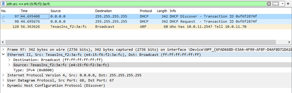
When I try to use "dhcp" command, the u-boot is trying a couple times but with no success.

Using Wireshark I can't see any traffic regarding ARP protocol.

What else should I do to make rmii work?

  • Hi,

    Which TI SDK did you start with?

    The register dump is showing a link detected. Could please explain how you changed the PHY register? Was with code or through the mii tool?

    Best Regards,

    Schuyler

  • Hi,

    I have changed in mux.c the mistake I have made:

    static struct module_pin_mux rmii1_pin_mux[] = {
            {OFFSET(mdio_clk), MODE(0) | PULLUP_EN},        /* MDIO_CLK */
            {OFFSET(mdio_data), MODE(0) | RXACTIVE | PULLUP_EN}, /* MDIO_DATA */
            {OFFSET(mii1_crs), MODE(1) | RXACTIVE},         /* MII1_CRS */
            {OFFSET(mii1_rxerr), MODE(1) | RXACTIVE},       /* MII1_RXERR */
            {OFFSET(mii1_txen), MODE(1)},                   /* MII1_TXEN */
            {OFFSET(mii1_txd1), MODE(1)},                   /* MII1_TXD1 */
            {OFFSET(mii1_txd0), MODE(1)},                   /* MII1_TXD0 */
            {OFFSET(mii1_rxd1), MODE(1) | RXACTIVE},        /* MII1_RXD1 */
            {OFFSET(mii1_rxd0), MODE(1) | RXACTIVE},        /* MII1_RXD0 */
            {OFFSET(rmii1_refclk), MODE(1) | RXACTIVE},     /* RMII1_REFCLK */
            {-1},
    };

    I'm using PROCESSOR-SDK-LINUX-AM335X  06_03_00_106.

    => mii read 1 0x17
    0049
    => mii write 1 0x17 0x61
    => mii read 1 0x17
    006D
    => mii read 1 0x17
    0065

    When I use "mii read 1 0x17" command as soon as u-boot starts, I get 0x49.

    I change the PHY register using "mii write 1 0x17 0x61" command in u-boot.

    After the change, when I use "mii read 1 0x17" command I get 0x65

    Best Regards,

    Maciej

  • Hi,

    Thank you for the information on the SDK used. I will need to consult with a colleague. Could you please attach the u-boot DTS file that you used? Did you try to boot to Linux and try the interface there? If so please attach the board DTS file that you used. For RMII the clocking source is important, could you please attach a snippet of the schematic showing the RMII1 and PHY interconnection?

    Best Regards,

    Schuyler

  • Hi Schuyler,

    I would like to join the conversation.
    Maciek is out of the office for a couple of days.

    Schuyler Patton said:
    Could you please attach the u-boot DTS file that you used?

    /*
     * Copyright (C) 2012 Texas Instruments Incorporated - http://www.ti.com/
     *
     * This program is free software; you can redistribute it and/or modify
     * it under the terms of the GNU General Public License version 2 as
     * published by the Free Software Foundation.
     */
    /dts-v1/;
    
    #include "am33xx.dtsi"
    #include "am335x-bone-common.dtsi"
    #include "am335x-evm-u-boot.dtsi"
    / {
    	model = "abc gateway_3_b";
    	compatible = "ti,am335x-bone-black", "ti,am335x-bone", "ti,am33xx";
    	chosen {
    		stdout-path = &uart0;
    		tick-timer = &timer2;
    	};
    };
    
    &ldo3_reg {
    	regulator-min-microvolt = <1800000>;
    	regulator-max-microvolt = <1800000>;
    	regulator-always-on;
    };
    
    &mmc1 {
    	vmmc-supply = <&vmmcsd_fixed>;
         	status = "okay";
            cd-gpios = <&gpio3 14 GPIO_ACTIVE_LOW>;
    };
    
    &mmc2 {
    	vmmc-supply = <&vmmcsd_fixed>;
    	pinctrl-names = "default";
    	pinctrl-0 = <&emmc_pins>;
    	bus-width = <8>;
    	status = "disabled";
    };
    
    &am33xx_pinmux {
      	mmc1_pins: pinmux_mmc1_pins {
                    pinctrl-single,pins = <
                          AM33XX_IOPAD(0x990, PIN_INPUT | MUX_MODE4) /* (A13) mcasp$ */
                    >;
            };
    };
    
    &lcdc {
    	status = "disabled";
    };
    
    / {
    	hdmi {
    		compatible = "ti,tilcdc,slave";
    		i2c = <&i2c0>;
    		pinctrl-names = "default", "off";
    		pinctrl-0 = <&nxp_hdmi_bonelt_pins>;
    		pinctrl-1 = <&nxp_hdmi_bonelt_off_pins>;
    		status = "okay";
    	};
    };
    
    &rtc {
    	system-power-controller;
    };
    

    Schuyler Patton said:
    could you please attach a snippet of the schematic showing the RMII1 and PHY interconnection?


    Schuyler Patton said:
    Did you try to boot to Linux and try the interface there?


    No, we didn't. Since we use a default bootstrap configuration, we have to program the PHY in U-boot and then boot Linux.
    We use the RMII master mode.
    The sequence we use to program the PHY is as follows:

    mii write 1 0D 1F
    mii write 1 0E 462
    mii write 1 0D 401F
    mii write 1 0E 4300

    mii write 1 17 61


    Regards

    Adam

  • Hi,

    I would suggest adding this line to the DTS file that you are using for your board. It is used to set the clocking mode necessary for the RMII interface. I am basing this on an example of the am335x-icev2 board. arch/arm/dts/am335x-icev2.dts.

    &phy_sel {

    rmii_clock-ext;

    }

    Best Regards,

    Schuyler

  • Hi Schuyler

    Thanks for the hint. After adding this property, things change a bit but unfortunately I still can't communicate via ETH.
    Please find the readings from the PHY registers both before and after setting the PHY. Once the PHY is configured, I see the expected 50MHz signal on the ETH0_RXD3_REFCLK (RMII Master mode).

    Before setting PHY
    0x0 - 0x3100
    0x1 - 0x786D
    0xB - 0x1000
    0x10 - 0x6912 / 0x6915
    0x17 - 0x0049
    0x467 - 0x0FCF
    0x468 - 0x0000

    Code I use to set PHY

    mii write 1 17 61
    mii write 1 0d 1f
    mii write 1 0e 462
    mii write 1 0d 401f
    mii write 1 0e 4300
    mii write 1 1f 4000

    After setting up PHY
    0x0 - 0x3100
    0x1 - 0x786D
    0xB - 0x1000
    0x10 - 0x2915 / 0x2D15
    0x17 - 0x0065
    0x467 - 0x0FCF
    0x468 - 0x0000

    What can I do to further troubleshoot this issue?

    Regards,
    Adam

  • Hi,

    After the change did you see any traffic with Wireshark?

    Could you also post the output of these commands:

    mii dump 1 0 

    mii dump 1 1

    Best Regards,

    Schuyler

  • Hi,

    Schuyler Patton said:
    After the change did you see any traffic with Wireshark?

    No, I didn't see any traffic with Wireshark.
    Moreover, I see some overflow detected in PHY, see
    register: 0x10
    value: 0x2D15

    Schuyler Patton said:

    Could you also post the output of these commands:

    mii dump 1 0 

    mii dump 1 1

    I don't have the exact copy of the "dump" command output but I have values from these registers

    register: 0x0
    value: 0x3100

    register: 0x1
    value: 0x786D

    The dump command adds only formatting to basic registers.

    Regards

    Adam

  • Hi,

    One more suggestion in addition to the one earlier to the board DTS file. Please try adding this to your u-boot Board DTS file:

    &cpsw_emac0 {

    phy-mode = "rmii";

    };

    This should set the MAC interface to RMII mode. After setting this DTS property please do not run the mii write commands setting modes. Let's see if the interface and PHY are initialized correctly with just this change.

    Best Regards,

    Schuyler

  • Hi,

    Schuyler Patton said:
    Please try adding this to your u-boot Board DTS

    I've already made this change directly in the am335x-bone-common.dtsi file.

    Schuyler Patton said:
    Let's see if the interface and PHY are initialized correctly with just this change.

    PHY is not set correctly.
    I see these values in the PHY registers:
    0x0 - 0x3100
    0x1 - 0x786D
    0xB - 0x1000
    0x10 - 0x6912 / 0x6915
    0x17 - 0x0049
    0x467 - 0x0FCF
    0x468 - 0x0000

    What do you mean by "see if the interface is initialized correctly"?
    What exactly do I have to check? and how?

    Regards
    Adam

  • Hi Schuyler,

    Do you have further information?

    Regards
    Adam

  • Hi, 

    I am checking with a colleague. Concerning initialization the scripting you are doing will have to be done prior to each network command I believe. I believe the driver should be all initialization and the mii commands should not be needed.

    For example, if you were to run 2 consecutive ping commands since u-boot is stateless the interface initialization will be performed again. If I am correct in the sequence I think you are issuing the mii commands and then the network command. The network command will completely initialize both the network interface and possibly the PHY causing the previously issued mii commands to be overwritten. 

    Best Regards,

    Schuyler

  • Hi,

    I don't quite understand what you were trying to explain.

    These mii commands I used, concerning only the PHY registers configuration.
    Stage 1)
    Once I invoke the following set of commands:

    U-Boot # mii write 1 17 61
    U-Boot # mii write 1 0d 1f
    U-Boot # mii write 1 0e 462
    U-Boot # mii write 1 0d 401f
    U-Boot # mii write 1 0e 4300
    U-Boot # mii write 1 1f 4000

    I see the 50MHz signal on the ETH0_RXD3_REFCLK.
    PHY is switched to RMII mode and is configured in master mode (PHY is a source of 50MHz reference clock).

    Stage 2)
    When I invoke "dhcp" command on the U-boot

    U-Boot # dhcp

    I don't see any traffic.

    Stage 3)
    The PHY is still configured according to Stage 1.
    Nothing has gone.
    When I read registers e.g.

    U-Boot # mii read 1 17

    I still see the previously issued settings.

    > The network command will completely initialize both the network interface and possibly the PHY causing the previously issued mii commands to be overwritten.

    According to what I wrote above, I don't think it's a true statement (at least for PHY).

    Regards
    Adam

  • Hi Schuyler,

    I think that I found how to narrow down the issue. I believe it will let you find a solution for my issue.

    Let's assume I use Beagle Bone Black (BBB) as my custom board.
    I use the fresh Linux SDK - 06_03_00_106.

    Step 1)
    I build MLO and u-boot using standard configuration "am335x_evm_defconfig".
    host# make ARCH=arm CROSS_COMPILE='arm-linux-gnueabihf-' mrproper
    host# make ARCH=arm CROSS_COMPILE='arm-linux-gnueabihf-' am335x_evm_defconfig
    host# make ARCH=arm CROSS_COMPILE='arm-linux-gnueabihf-'

    I boot BBB to see results.
    => mii info
    PHY 0x00: OUI = 0x01F0, Model = 0x0F, Rev = 0x01, 100baseT, FDX
    => setenv autoload no
    => dhcp
    link up on port 0, speed 100, full duplex
    BOOTP broadcast 1
    DHCP client bound to address 10.0.11.70 (3 ms)

    Conclusions:
    DHCP is working properly on u-boot when I use the default configuration.

    Step 2)
    I prepare an u-boot configuration for my custom board according to
    software-dl.ti.com/.../U-Boot.html
    6.4.1.2.1. Creating an initial baseline by cloning and flattening TI EVM support
    Since I use BBB as my custom board, I can minimize the number of changes and I can omit some steps (from the above-mentioned tutorial) as follows:
    1.1 - done
    1.2 - done
    1.3 - done
    1.4 - skipped, I use BBB as my custom board
    1.5 - done
    2.1 - done
    2.2 - done
    2.3 - done
    2.4 - skipped, I use BBB as my custom board
    2.5 - skipped, I use BBB as my custom board
    2.6 - skipped, I use BBB as my custom board
    2.7 - done
    3.1 - done
    3.2 - done
    3.3 - skipped, I use BBB as my custom board
    3.4 - skipped, I use BBB as my custom board
    3.5 - done
    4.1 - done
    4.2 - done
    4.3 - done
    4.4 - done
    5.1 - done
    5.2 - skipped, to see results at this step

    I build MLO and u-boot using custom configuration "am335x_custom_defconfig".
    host# make ARCH=arm CROSS_COMPILE='arm-linux-gnueabihf-' mrproper
    host# make ARCH=arm CROSS_COMPILE='arm-linux-gnueabihf-' am335x_custom_defconfig
    host# make ARCH=arm CROSS_COMPILE='arm-linux-gnueabihf-'

    I boot BBB to see results.
    => mii info
    PHY 0x00: OUI = 0x01F0, Model = 0x0F, Rev = 0x01, 100baseT, FDX
    => setenv autoload no
    => dhcp
    link up on port 0, speed 100, full duplex
    BOOTP broadcast 1
    DHCP client bound to address 10.0.11.70 (3 ms)

    Conclusions:
    DHCP is working properly on u-boot when I use the configuration from step 2.

    Step 3)
    I add changes from 5.2 (intentionally skipped on the previous step) to complete custom configuration.
    Since I didn't remove BOARD_DETECT functionality, I have to additionaly copy /board/ti/common/* to my /board/{company}/common/* directory.
    At this point I have fully cloned EVM configuration under the newly established name.

    I build MLO and u-boot as in step 2 to see results.

    I boot BBB to see results.
    => mii info
    PHY 0x00: OUI = 0x01F0, Model = 0x0F, Rev = 0x01, 100baseT, FDX
    => setenv autoload no
    => dhcp
    link up on port 0, speed 100, full duplex
    BOOTP broadcast 1
    BOOTP broadcast 2
    BOOTP broadcast 3
    BOOTP broadcast 4
    BOOTP broadcast 5
    BOOTP broadcast 6
    BOOTP broadcast 7
    BOOTP broadcast 8

    Abort

    Conclusions:
    DHCP has stopped working properly on u-boot when I used this configuration (step 3).

    -----------------

    I think it may be connected with my issue.
    There is probably something "hardcoded" in sources and it's missed in this above-mentioned tutorial.

    How to solve this problem?


    Regards
    Adam

  • Hi, 

    Thanks for updating the thread on where the issue might be. I will consult with a colleague on where the issue is. Out of curiosity are you able to use wireshark to see if there are any packets coming out?

    Best Regards,

    Schuyler

  • Hi,

    Schuyler Patton said:
    Out of curiosity are you able to use Wireshark to see if there are any packets coming out?

    Yes, I use Wireshark to capture traffic in the network.
    Unfortunately, there are no packets coming out the custom board (DP83822I connected via RMII master mode).

    -------------
    Moreover I did a test on BBB to have a reference point.

    On the reference board (BBB), when I invoke:

    => setenv autoload no
    => dhcp
    link up on port 0, speed 100, full duplex
    BOOTP broadcast 1
    DHCP client bound to address 10.0.11.70 (3 ms)
    => ping 10.0.11.254
    link up on port 0, speed 100, full duplex
    Using ethernet@4a100000 device
    host 10.0.11.254 is alive

    I get following packets captured in Wireshark:

    Regards

    Adam