This thread has been locked.

If you have a related question, please click the "Ask a related question" button in the top right corner. The newly created question will be automatically linked to this question.

AM5728: Power connection with TPS6590371

Part Number: AM5728
Other Parts Discussed in Thread: TPS659037,

Our customer has an issue with their boards in mass production designed with TPS6590371 a few years ago. The issue is discussed in the thread here: https://e2e.ti.com/support/processors/f/791/t/945139

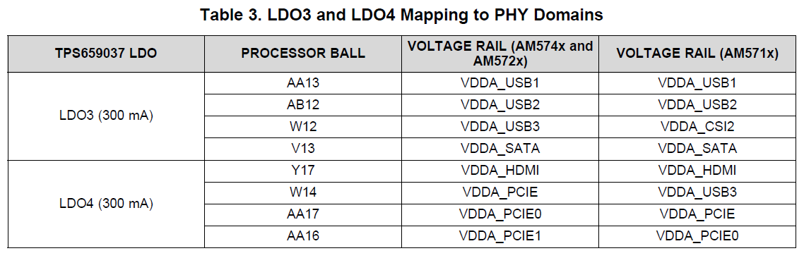
The current user guide for the power connection with TPS659037 describes for TPS6590378ZWSR and TPS6590379ZWSR the mapping of LDO3 and LDO4 to PHY Domains.

TPS659037 user's guide to power AM574x, AM572x, and AM571x (Rev. F)
https://www.ti.com/lit/ug/sliu011f/sliu011f.pdf

Their boards designed with TPS6590371 have different mapping, are there any problems in that case?

Best regards,

Daisuke

  • Hi,

    On the customer's board, LDO3 is connected to all PHY Domains and LDO4 is unused because USB3, PCIe and HDMI features are unused.

    Is this connection inappropriate?

    Can the load current exceed the rated output current?

    Best regards,

    Daisuke

  • Hi,

    Daisuke Maeda said:

    On the customer's board, LDO3 is connected to all PHY Domains and LDO4 is unused because USB3, PCIe and HDMI features are unused.

    Is this connection inappropriate?

    Can the load current exceed the rated output current?

    In the approved and validated power supply connections (Table 8-1) on the datasheet, LDO3 and LDO4 are used for the PHY Domains.

    Should a separate analysis be performed for their board to ensure that the load current does not exceed the rated output current of LDO3?

    Best regards,

    Daisuke

  • Daisuke,

    Is the customer still using TPS6590371 or have they switched to something newer?  Looking through my various documentation revisions, user guides, etc. it looks like:

    1. The TPS6590371 transitioned to TPS6590373.  The only difference between these two is when the VBUS is present, TPS6590371ZWSR unexpectedly shuts down during a warm reset.

    2. The TPS6590373 transitioned to TPS6590374.  This looks like the point in time where LDO4 was introduced and the 1.8V PHY rails were split across two different LDO's.  I didn't see any other changes.

    3. The TPS6590374 transitioned to the TPS6590376.  The default voltages were updated to coincide with AM572x Rev 2.0 silicon and future variants.

    4. The TPS6590376 transitioned to the TPS6590378 to fix a power down sequencing issue.

    Daisuke Maeda said:
    Should a separate analysis be performed for their board to ensure that the load current does not exceed the rated output current of LDO3?

    Yes, but that should be simple.  Based on your description it sounds like the only peripheral actually being used is SATA.  Since LDO3 (even in the latest designs) powers both USB and SATA, I don't see any issues.

    Best regards,
    Brad

  • Daisuke Maeda said:
    On the customer's board, LDO3 is connected to all PHY Domains and LDO4 is unused because USB3, PCIe and HDMI features are unused.

    Does LDO4 have a capacitor on the output?  At a minimum they should adjust their board to have a capacitor on LDO4 so that it remains stable when transitioning to the TPS6590378.

  • Daisuke Maeda said:
    Their boards designed with TPS6590371

    I assume they're using Rev 2.0 silicon of the AM5728?  If so, the TPS6590371 does not have the correct default voltages and so you are violating the processor data sheet requirements.

  • Hi Brad-san,

    Thank you for your reply.

    The device markings for AM5728 and TPS659037 used by our customer are as follows.

    AM5728BABCXA
    86ZCV29
    842 ABC G1

    AM5728 is SR2.0.

    TPS659037
    OTP 94 L3
    63AYH6W G2 G1

    Does this marking indicate TPS6590371?

    Best regards,

    Daisuke

  • Daisuke-san,

    Is there a TI FAE to whom you can send the schematic?  That part number appears to be a custom OTP.  We would need to review the schematic and the OTP definition together to make sure that everything is consistent and correct.

    Best regards,
    Brad

  • Hi Brad-san,

    Thank you for your reply.

    I requested our customer to present their schematic.

    I will notify this thread to local TI FAE.

    Best regards,

    Daisuke

  • Hi Brad-san,

    It is not easy for the customer to present their schematic due to their internal rules, so first of all, the customer will discuss this issue with our local TI FAE.

    Best regards,

    Daisuke

  • Hi Brad-san,

    Our customer found that some of SATA_PHY_RX registers were incorrectly set in BSP source codes and fixed it. As a result, the issue that SATA PHY communication not established has not occurred so far.

    Best regards,

    Daisuke