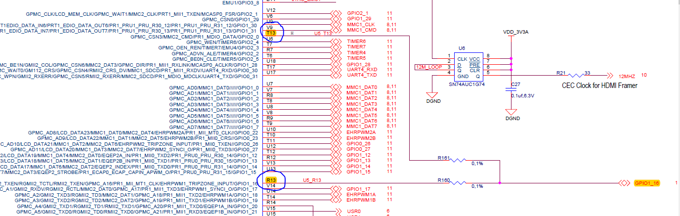
With reference to the BeagleBone Schematic, we see that some of the GPIOs are connected to each other through 0 ohm resistors before coming to the expansion headers.
What is the intention behind this?
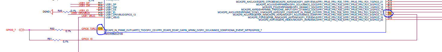
With reference to the BeagleBone Schematic, we see that some of the GPIOs are connected to each other through 0 ohm resistors before coming to the expansion headers.
What is the intention behind this?