

Hi All,
I would like to ask some questions on pin connection.
I used Excel’s conditional formatting to highlight pins according to their types and obtained a colored pin map (top view) like below:
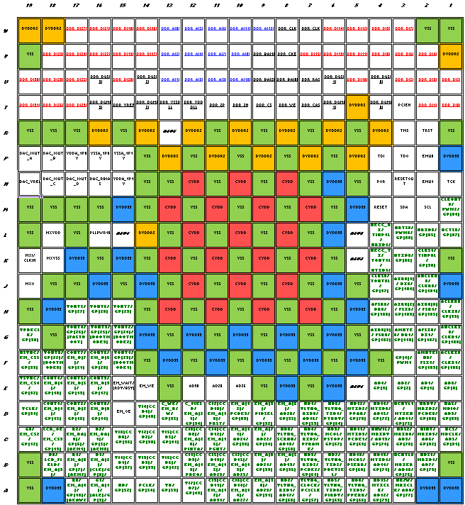
All those cells in solid color are supply or ground pins:
1. VSS = green
2. DVDDR2 = orange
3. DVDD33 = blue
4. CVDD = red
And all those underlined are DDR2 related pins. Are those with bold font in deep green are pins that are multiplexed with GPIO.
My question is how should I deal with unused pins? I do not have an idea with pins that are
1. Unused
2. Not multiplexed GPIO
yet, but with unused GPIO pins, since its I/O direction can be toggled by program, I think it is bad to leave it as an input for which external signal could affect its logic gate, so mostly likely I should toggle it as OUTPUT, and leave it unconnected.
Is it correct? Or should I set it as output, and either
1. Set value high, and connect to DVDD33
2. Set value low, and connect to VSS
?
Which is recommended?
On the other hand, I have found that most of GPIO multiplexed pins have either IPD or IPU. If they already have pulling resistors, does this mean I can also safely
1. Set them as INPUT
2. And
i. Connect to DVDD33 if it has IPU
ii. Connect to VSS if it has IPD
Logically, all the above solutions (either as OUTPUT or INPUT and making their associated connections) seem would work. But practically, which is better? What is TI’s recommendation?
My last question is on IPU and IPD resistors. Since pins with such description are described as having the ability to internally turn on a puling resistor, then how large resistance (in Ohm) does these resistors offer? Since they are situated within the silicon ship, then it seems unlikely that they can be made using material of common external ZWT or through-hole resistors, so what are they made of? Someone told me that they are something like “MOS resistor”, is it true?
And for GPIO pins with IPD or IPU, do I still need to connect an external pulling resistor when they are used as input pins?
Thanks,
Zheng

