Other Parts Discussed in Thread: AM5749, AM5748
Hello support!
I would like to know how to use pinmux tool.
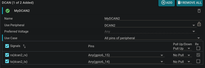
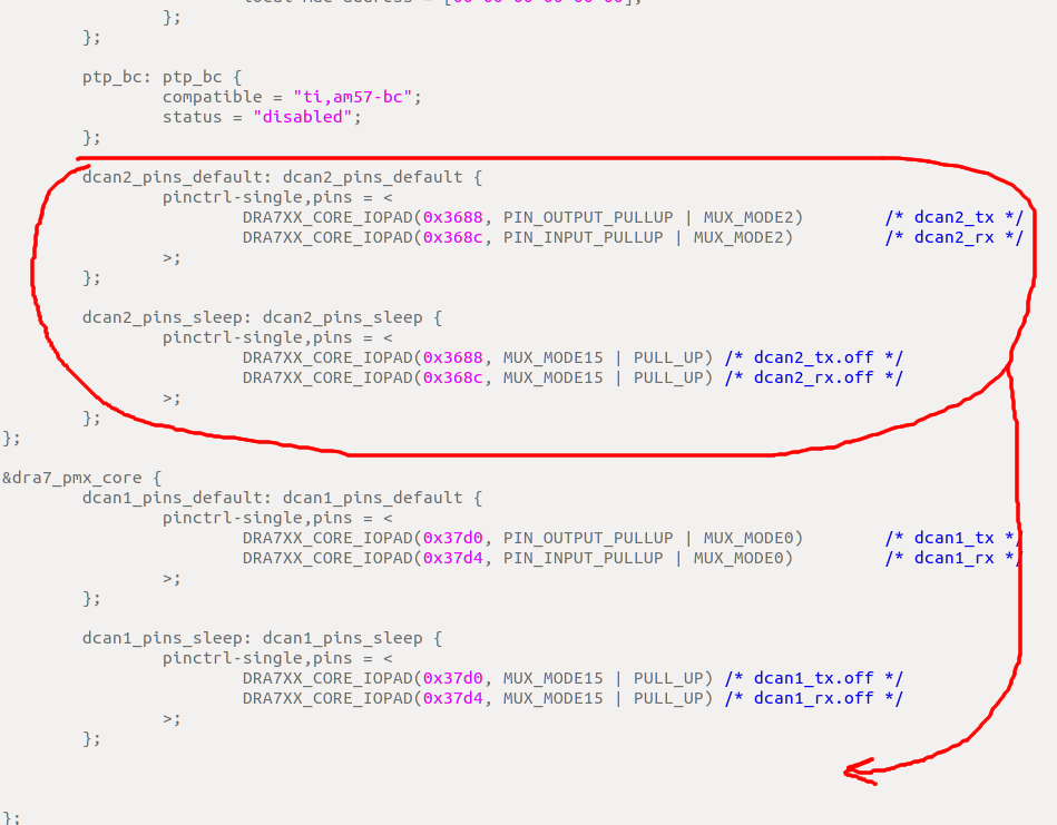
I mean I wold like to add dcan2 for example.
1.You still didn't get am5749
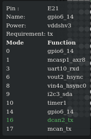
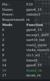
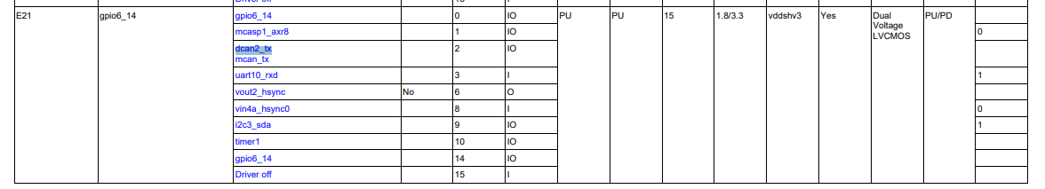
2.I chose what I want for example:
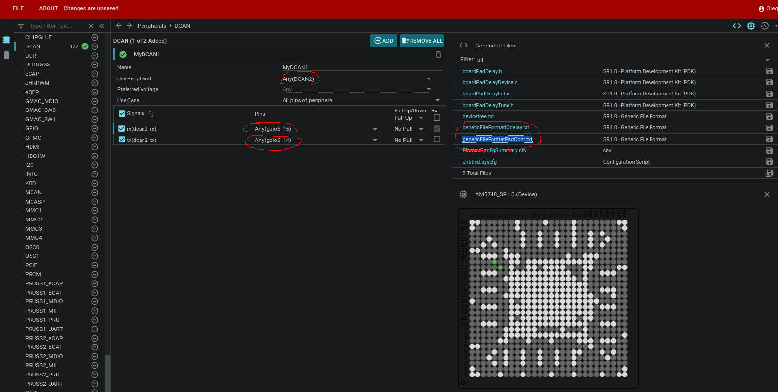
3.Like I understood I should use some script for generating code from this files(genericFileFormatPadConf.txt and genericFileFormatPadConf.txt). I should get some file and integrate this code in mux_data.h
it is will be something for: const struct pad_conf_entry core_padconf_array_essential_am574x_idk and for const struct iodelay_cfg_entry iodelay_cfg_array_am574x_idk.
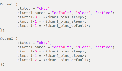
4.In devicetree.txt I will get code for Device tree obvious.
So which scrip I should use where I should get it?
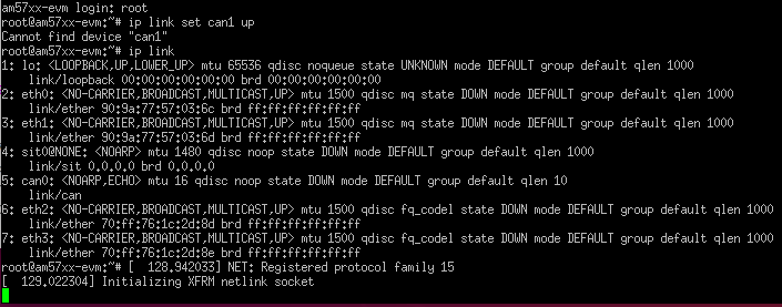
I will try to download something but it doesn't generate code for 2 files.
BR,
Oleg