


Part Number: TDA4VM
Hi,
We want to test the PCIe communication between two TDA4 chips, marked TDA4_A, TDA4_B, and transfer image data between the two TDA4 chips through the PCIe interface.
The PCIe clock TDA4_A on our hardware provides the clock to TDA4_B. The circuit schematic diagram is as follows:
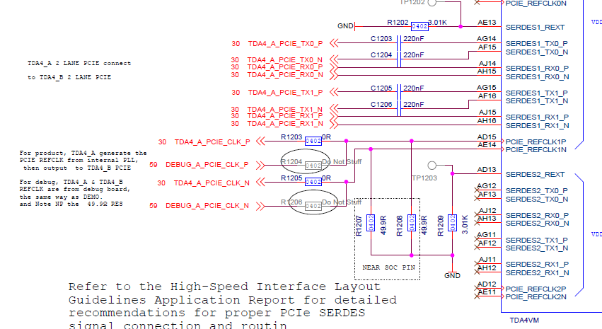
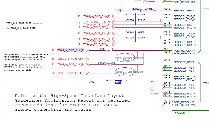
At the same time, we can also choose to provide clocks to the PCIe interfaces of TDA4_A and TDA4_B through an external clock by use R3004 and R3006.
When using an external clock, we follow the method in section 3.2.2.8 of ti-processor-sdk-linux-automotive-j7-evm-07_00_00 userguide. TDA4_A uses rc mode, TDA4_B uses ep mode, and TDA4_A can correctly read the nodes of TDA4_B .
But when we use TDA4_A to provide a clock to TDA4_B, TDA4_A uses rc mode, TDA4_B uses ep mode, and TDA4_A cannot read the nodes of TDA4_B.
Questions are as follows
1. Use TDA4_A to provide clock to TDA4_B, what do we need to modify to realize the function of TDA4_A and TDA4_B PCIe communication?
2. In the userguide Multi-chip Video-Capture Application using PCIe Backplane example of vision_app of psdk_rtos_auto_j7_06_02_00_21, I can realize image transmission between two TDA4s. But the two TDA4s are in RC mode, and a TDA4 is needed as a backplane.
If my TDA4_A is configured as RC and TDA4_B is configured as EP, are there any relevant examples to realize the image transmission of both? If not, how can we modify the Multi-chip Video-Capture Application example to achieve this function?
Best Regards!
Kepei


