This thread has been locked.

If you have a related question, please click the "Ask a related question" button in the top right corner. The newly created question will be automatically linked to this question.

Chaining previewer & resizer together on dm6435


I am still working on trying to push on image through the previewer and resizer in one pass, and I'm getting an output image that looks like a scrambled version of the input, so obviously I haven't set some register up correctly.  Question:

Do the horizontal/vertical input size registers of the resizer have to exactly match the horizontal/vertical output sizes of the previewer?

  • After some further fiddling, I got the correct image out of the previewer/resizer in one pass.  My initial question still stands, but I have run into a secondary problem.  The first pass works, but for subsequent passes the busy bit in the resizer pcr never clears.  It reads clear after the first pass.  I poll the interrupt controller event for the resizer to determine completion, and I clear that interrupt flag before trying again.  I have looked at registers for both the previewer & resizer, and the busy bit not clearing is the only difference.  Am I missing anything?

    Here is the code.  Buffer width is always a multiple of 32 bytes.

    Int32 previewerResizerCombo(Uint8 *get, Uint8 *put, Int16 height, Int16 bufferWidth, Int16 inputWidth)
    {

        Int32 timedOut = 0;


        // Setup previewer registers
        VPFE_PREV_PCR =    0 |
                    (1  << 26) |    // Gamma bypass (1 = bypass, 0 = gamma correct)
                    (0  << 22) |    // Shade shift (1 = enable, 0 = disable)
                    (0  << 20) |    // SDRAM port output ( 1 = enable, 0 = disable)
                    (1  << 19) |    // Resizer port ( 1 - output to resizer)
                    (0  << 17) |     // YC position (0 YCrYCb, 1 YCbYCr, 2 CbYCrY, 3 CrYCbY)
                    (0  << 16) |    // Color suppression (1 - enable, 0 - disable)
                    (0  << 15) |    // non-linear enhancer (1 - enable, 0 - disable)
                    (1  << 10) |    // CFA (bayer interp)(1 - enable, 0 - disable)
                    (0  << 9)  |    // noise filter (1 - enable, 0 - disable)
                    (0  << 8)  |    // Horz median filter (1 - enable, 0 - disable)
                    (0  << 7)  |    // dark frame capture (1 - capture dark frame, 0 - normal)
                    (0  << 6)  |    // subtract dark frame (1 - enable, 0 - disable)
                    (0  << 5)  |    // Inverse A-law (1 - enable, 0 - disable)
                    (1  << 4)  |    // Input data width (1 - 8 bit, 0 - 10 bit)
                    (1  << 3)  |    // One shot mode (1 one shot, 0 - continuous)
                    (1  << 2)  |    // Source (1 - sdram, 0 - CCD controller)
                    (0  << 1)  |    // Busy bit
                    (0  << 0);        // Preview enabled (do this last after others are set)

        VPFE_PREV_HORZ_INFO = 0 |
                    (0 << 16)  |        // start pixel horizontal
                    (inputWidth - 1);    // end pixel horizontal

        VPFE_PREV_VERT_INFO = 0 |
                    (0 << 16)  |    // start line vertical
                    (height - 1);    // end line vertical

        VPFE_PREV_RSDR_ADDR = (Uint32)get;        // must be 32 byte aligned
        VPFE_PREV_RADR_OFFSET = bufferWidth;    // must be 32 byte aligned
        VPFE_PREV_WSDR_ADDR = 0;
        VPFE_PREV_WADD_OFFSET = 0;

        // Setup resizer registers
        VPFE_RESZ_RSZ_CNT =    0  |
                    (0    << 29) |        // cbilin (0 = same as lum, 1 = bilinear interpolation)
                    (0    << 28) |        // input source (0 = preview engine, 1 = sdram)
                    (0    << 27) |        // input type (0 = yuv422interleaved, 1 = color separate)
                    (0    << 26) |        // ycpos (0 = YC, 1 = CY)
                    (0     << 23) |        // vertical starting phase (0-7)
                    (0     << 20) |        // horizontal starting phase (0-7)
                    ((512-1) << 10)    |    // vertical resizing, 64-1024, 64 = 1/4, 256 = 1, 1024 = 4x
                    ((512-1) <<  0);    // horizontal resizing, 64-1024, 64 = 1/4, 256 = 1, 1024 = 4x


        VPFE_RESZ_OUT_SIZE = ((((height - 8) / 2)) << 16) |
                             ((inputWidth - 12) / 2);

        VPFE_RESZ_IN_START =     (0     << 16)    |    // vertical starting line. must be 0 if input is SRAM
                                (2  << 0);        // horizontal starting pixel (bytes)

        VPFE_RESZ_IN_SIZE    =     ((height - 4) << 16)    |    // input height, constrained by special equation
                                  ((inputWidth - 5) << 0);        // input width, constrained by special equation

        VPFE_RESZ_SDR_INADD = 0;    // must be 32 byte aligned
        VPFE_RESZ_SDR_INOFF = 0;    // must be 32 byte aligned, # bytes means pixels x 2
        VPFE_RESZ_SDR_OUTADD = (Uint32)put;                    // must be 32 byte aligned
        VPFE_RESZ_SDR_OUTOFF = (Uint32)(bufferWidth);        // must be 32 byte aligned, # bytes means pixels x 2 (@ half res = x1)
        VPFE_RESZ_YENH = 0;


        VPFE_RESZ_PCR = 0x01;    // turn on resizer

        // Trigger start
        VPFE_PREV_PCR |= 1;

        // Wait for finish/timeout
        startTimeoutTimer(RESIZER_TIMEOUT);
        while ( (0 == (INTC_EVTFLAG0 & (1 << 30))) && (0 == (timedOut = getTimeoutStatus())) );    // wait for resizer to complete
        stopTimeoutTimer();
        INTC_EVTCLR0 =     (1 << 30) | // clear resizer interrupt signal
                        (1 << 29); // clear previewer interrupt signal

        if (timedOut == 0) {
            return 0;
        } else {
            return -1;    // to do : we will need to recover from this
        }
    }

  • Are you clearing VPSS PCR WBL bits [VPFE user guide page #200] based on your usage? I am not sure wether this is the actual reason for previewer/resizer being busy. Give a try.

  • MattLipsey said:
    The first pass works, but for subsequent passes the busy bit in the resizer pcr never clears. 

    What is status of Previewer busy bit (PCR.BUSY)? If that is also set, then make sure that FMTCFG.VPEN bit of CCDC is not set. It should be 0 to disable the video port.


  • VPSS PCR WBL bits are all zero after the first execution, and still all zero after the failed execution, so I don't think that is the problem.

    Previewer PCR.BUSY is 0 after first call and after failed second call.

    I'm running out of places to look to tell me the nature of the problem.  Here is the code snippet that I call once at startup.  Again, cfa interpolation is the only thing I enabled in the previewer, the commented out registers are just unused placeholders in case I added other modules.

    void initPreviewer()
    {
        Int32 i;
    //    Uint32 dar;     // uncomment this line (and section below) to readback previewer cfa constants
        volatile Uint32 *vReg, *hReg;
        Uint32 regEntry;

        // =================================================
        // Unless stated otherwise, all previewer constants
        //    are lifted from the ti psp library example
        //   " psp_bios_vpfe_st_on_the_fly_sample.c "
        // =================================================

        VPFE_PREV_PCR &= ~(0x01);    // disable previewer engine prior to changing values

        VPSS_SDR_REG_EXP = 0x200 << 20;    // read delay register    // to do: tune this

        VPFE_PREV_AVE = 0x14; //0x14 for no avg, 0x15 for x2 avg
        //VPFE_PREV_HMED
        //VPFE_PREV_NF
        //VPFE_PREV_WB_DGAIN
        //VPFE_PREV_WBGAIN
        //VPFE_PREV_WBSEL
        VPFE_PREV_CFA = (0x28 << 16) | (0x28);
        VPFE_PREV_BLKADJOFF = 0;

        VPFE_PREV_RGB_MAT1 = 0x100;                // use unity blend matrix until we come up with a better one
        VPFE_PREV_RGB_MAT2 = 0;
        VPFE_PREV_RGB_MAT3 = 0x100;
        VPFE_PREV_RGB_MAT4 = 0;
        VPFE_PREV_RGB_MAT5 = 0x100;
        VPFE_PREV_RGB_OFF1 = 0;
        VPFE_PREV_RGB_OFF2 = 0;

        VPFE_PREV_CSC0 = (    (0x04C <<  0) |
                            (0x096 << 10) |
                            (0x01D << 20)    );

        VPFE_PREV_CSC1 = (    (0x3d4 <<  0) |
                            (0x3ac << 10) |
                            (0x082 << 20)    );

        VPFE_PREV_CSC2 = (    (0x082 <<  0) |
                            (0x395 << 10) |
                            (0x3eb << 20)    );

        VPFE_PREV_CSC_OFFSET = 0;

        VPFE_PREV_CNT_BRT = (0x10 << 8) | 0;    // contrast gain (u8q4) / brightness offset
    //    VPFE_PREV_CSUP
    //    VPFE_PREV_SETUP_YC

        VPFE_PREV_SET_TBL_ADDR = 0x1400;    // start of cfa coef table
        for(i = 0; i < PSP_PREVIEWER_CFA_COEFF_TABLE_SIZE; i++) {
            VPFE_PREV_SET_TBL_DATA = (Uint32)cfa_coef[i];
        }

        // use this code to verify constants were written
    //    VPFE_PREV_SET_TBL_ADDR = 0x1400;    // start of cfa coef table
    //    for(i = 0; i < PSP_PREVIEWER_CFA_COEFF_TABLE_SIZE; i++) {
    //        dar = VPFE_PREV_SET_TBL_DATA;
    //        if (dar != (Uint8)cfa_coef[i]) {
    //                yuvCanvas[0] = 69;
    //         }
    //    }

        vReg = &VPFE_RESZ_VFILT10;
        hReg = &VPFE_RESZ_HFILT10;

        // Since we are downres 50%, horizontal & vertical filter coefficients are identical
        for (i = 0; i < 16; i++) {
            regEntry = resizer_coef[i * 2] | (resizer_coef[(i * 2) + 1] << 16);
            *vReg++ = regEntry;
            *hReg++ = regEntry;
        }


    }

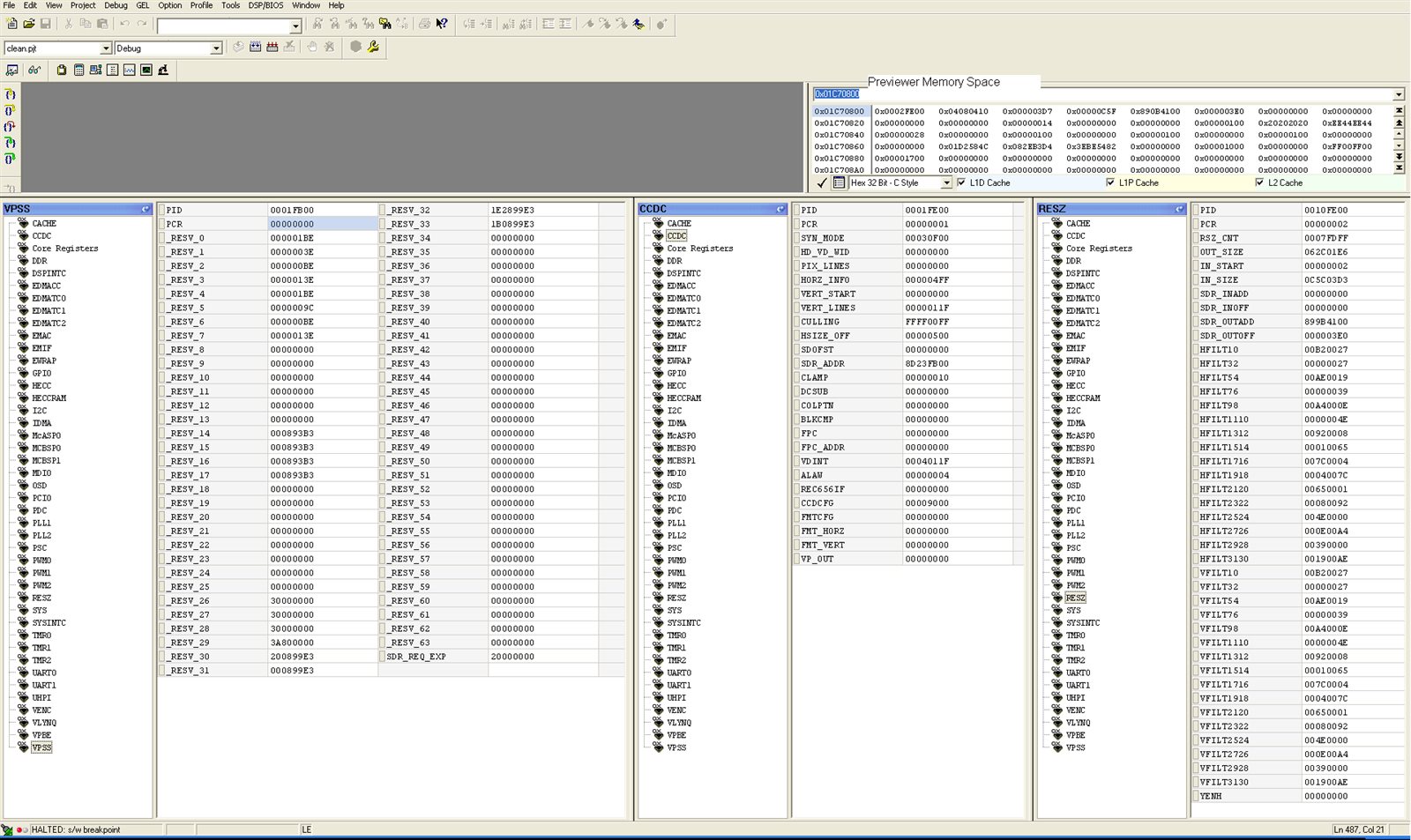
  • This is a screenshot of relevant registers after the timeout failure.  I had to open a memory window to the previewer registers, code composer did not have them in the register list.  I should note that the ccdc is enabled but not active during this time.

  • MattLipsey,

    PCR register settings of PREVIEWER indicate that PREVIEWER is configured in CONTINOUS mode, can you check that?

  • remember that the ONESHOT bit resets to 0 every time the enable bit is asserted.  It is set in the code.

  • In the absence of a definite answer, I am trying to verify all my calculations.  From SPRAI7 section 4.1, I get the equations for setting the input height/width registers as:

    iw = (32 * sph + (ow - 1) * hrsz + 16) >> 8 + 7

    ih = (32 * spv + (oh - 1) * vrsz + 16) >> 8 + 4

    I know that am using the 4 tap, 8-phase filter because my hrsz & vrsz are 512, so according to section 3.4 that means 4 taps.

    Because I have a targeted output width, I solve for input width in terms of output width.  Using sph = 0 & hrsz = 512, that reduces the equation to:

    iw = floor((ow * 2) + 5)

    ih = floor((oh * w) + 2)

    Correct?  These values are then programmed into the IN_SIZE resizer register.  I still haven't received an answer to my original question:  do I have to exactly match the previewer output to these values?  I could only get a good looking output image when I tried to do that, so without a definitive answer, I assumed that to be so.

    I'm going to continue to go backwards through the register settings, but I wanted to post this first in case I made a mistake in my assumptions.

    edit: oops, I replaced the iw & ih values with the correct multiply operation instead of the incorrect division

  • OK, I found my issue and I can run this repeatedly with different input widtths.  Apparently I had miscalculated the calculations for setting the out size register.  Should have been:

        VPFE_RESZ_OUT_SIZE = (((height - 6) / 2) << 16) |
                             ((inputWidth - 10) / 2);

    Don't know if that will help anyone else or not.

  • thanks for sharing..glad to know that you solved the issue