Hi,
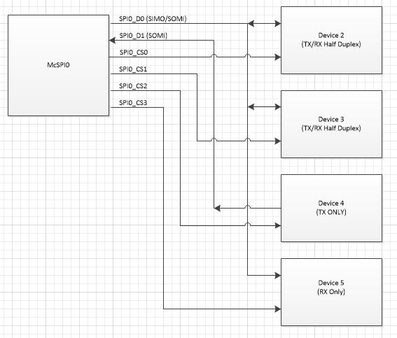
my design need connect the am3358 with 6 SPI slave devices, I try to use the McSPI module inside the am3358, attached is my diagram, could you help to confirm the McSPI can support this kind of design?
thanks,
Li
Hi,
my design need connect the am3358 with 6 SPI slave devices, I try to use the McSPI module inside the am3358, attached is my diagram, could you help to confirm the McSPI can support this kind of design?
thanks,
Li