This thread has been locked.

If you have a related question, please click the "Ask a related question" button in the top right corner. The newly created question will be automatically linked to this question.

PROCESSOR-SDK-DRA8X-TDA4X: TDA4x DDR4 Layout Guidelines

Part Number: PROCESSOR-SDK-DRA8X-TDA4X

Hello,

I have a question in the TDA4x DDR4 Layout Guidelines document.

Please refer to the attached chart
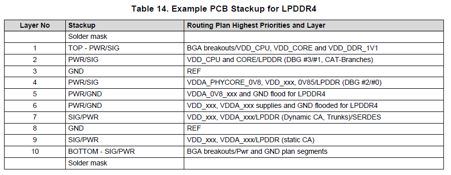
Questions.

1. Does it mean to place each power source in the corresponding layer?

2. I made the board first, but DDR4 doesn't work smoothly at 800Mhz or higher.

    Where do you care about the most in the artwork?

  • Hi,

    I am forwarding your first question.

    Can you give more description as to what is meant by "doesn't work smoothly at 800Mhz or higher"?

    For instance,

    1. Is this the data rate or clock frequency?
    2. What type of failures do you see?
    3. Does it work robustly (boot an OS, run your application, etc.) at slower speeds?

    Also, what code base are you using for testing (u-boot? RTOS?), and did you use the latest XLS register configuration tool  (0.5.0) to generate register settings at the different frequencies?

    Thanks,
    Kevin

  • Hello,

    Answer your questions

       1. DDR4 Clock frequency

       2. Stops during booting or stops after booting is complete

       3. DDR4 Clock works perfectly at 800MHz

    First of all, due to the tight schedule, we are reproducing the PCB by revising the artwork by referring to the DDR4 design guidelines.

    Due to the PCB STACK-UP structure, there is a section where impedance cannot be matched I'm worri

    Thanks,

    Intack Jeon

  • The PCB design is CRITICAL to achieve full data rate of the LPDDR4 interface.  Yes - the guidelines provide an example stack-up including which layers to route power and signals.  This recommendation is to help improve both signal and power integrity - both of which are critical for LPDDR4.  All of the guidelines sections are important - including the simulation section.  We strongly recommend 3D simulations be run on PCB design to help ensure successful design.

  • Hello,

    I have one more question.

    The DDR4 wiring on the first board is designed as a single 50 ohm differential 100 ohm.

    This time, I used a single 35 ohm, 40 ohm, and differential 80 ohm to do the artwork by referring to the design guide.

    Will this alone help improve performance?

    Thank,

    Intack Jeon

  • We do recommended routing the LPDDR4 traces at lower impedances as you specified.  I cannot answer if it will help improve your performance, as I do not have any specifics about your existing layout or the analysis that shows what is causing the failures at higher speeds.

  • DDR4 is perfectly driven by changing PCB stack_up


    Thanks for your help