This thread has been locked.

If you have a related question, please click the "Ask a related question" button in the top right corner. The newly created question will be automatically linked to this question.

AM3352: USB SI issue

Part Number: AM3352

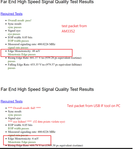
We have a problem in edge monotonicity of USB SI testing. The value tested is around 48mv~6xmv. (criteria is max 50mv).

  • Since the USB port is the host port of the AM3352, so the test packet is generated from AM3352.
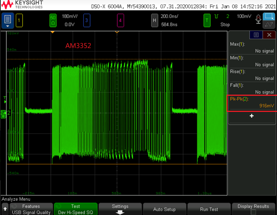
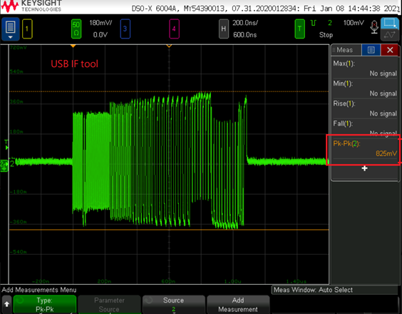
  • We have compared the test packet between AM3352 generated and PC generated. Found that the waveform amplitude from AM3352 is larger than USB IF tool generated. The shapes are also slightly different. 
  • Can you please give us recommendations how to improve the edge monotonicity of USB SI?

Waveform from AM3352:

Waveform from USB IF Tool:

Thanks,

Nick

  • The USB-IF tool sends a test command from the PC host to the attached device that tells it to enter test mode and begin transmitting the test packets. Typically, a test fixture is inserted in the path where it plugs directly into the device connector such that it is located close to the source. A switch on the test fixture is toggled once the device begins transmitting repeated test packets. The switch disconnects the host PC and attached cable from the device and connects ideal termination resistors to the signals. The scope is attached to the USB signals on the test fixture near the termination resistors. This test is considered a near end test and can be used to show combined performance of the device transmitter and device PCB signal routing to the connector. The only time you should see non-monotonic transitions is when you have an impedance discontinuity in your PCB traces. If you try to measure the test packet on the far end of a cable segment, the performance of the cable enter must also be considered.

    Typically, non-monotonic transitions occur when there is a impedance discontinuity and reflections from a previous transition returns from the discontinuity and interferes with the current signal transition.  It is very unlikely your observation is the result of a device issue. 

    Regards,
    Paul

  • Thank you, that makes sense. 

    One thing that is still unclear is why the test packet from AM3352 is slightly different from PC.

    We're assuming the AM3352 is following USB-IF to generate the test packet, is that correct?

    Thanks,

    Nick

  • It has been many years since I ran USB 2.0 tests.  I only remember the USB-IF tool being used to initiate test packets from an attached devices.

    Are you sure the two waveforms represent device and host sending test packets?  I suspect the device is sending the test packet in both, but one waveform represents the signal while still connected to the cable and host before the test fixture switch is toggled, which disconnects the host and applies an ideal load. The first waveform looks like what you would see when terminated with the correct load and the second one looks like the cable and host are still connected.

    Is there a chance your customer doesn't fully understand how the test works and making wrong assumptions about the waveforms?

    Does the person performing the test have experience running it on previous devices? Have they tried connecting another high-speed device to their test platform to validate their test setup?

    Regards,
    Paul