This thread has been locked.

If you have a related question, please click the "Ask a related question" button in the top right corner. The newly created question will be automatically linked to this question.

J721EXSOMXEVM: Linux Driver for TCAN1044-Q1 CAN transceiver

Part Number: J721EXSOMXEVM
Other Parts Discussed in Thread: TCAN1044-Q1

Hello,

We have Custom J7 board which has 2X TCAN1044-Q1 CAN transceiver and they are mapped to MCAN0 & MCAN6. I am using SDK 7.0, I did not find any Linux Driver for it. Could you please let me know following -

1) Is there a device driver available for TCAN1044-Q1 for Linux on A72 core? If yes could you please let me know where can I find it?

2) In order to verify our circuit/electrical connection. How can ping or reset this transceiver without device driver from A72 core/LInux? 

3) For our use case pinmux tool generated following nodes for CAN0 & CAN6. 

	can6_faceplate_pins_default: can6_faceplate_pins_default {
		pinctrl-single,pins = <
			J721E_IOPAD(0x44, PIN_INPUT, 6) /* (AE24) PRG1_PRU0_GPO16.MCAN6_RX */
			J721E_IOPAD(0x40, PIN_OUTPUT, 6) /* (AC24) PRG1_PRU0_GPO15.MCAN6_TX */
		>;
	};

	can0_faceplate_pins_default: can0_faceplate_pins_default {
		pinctrl-single,pins = <
			J721E_IOPAD(0x208, PIN_INPUT, 0) /* (W5) MCAN0_RX */
			J721E_IOPAD(0x20c, PIN_OUTPUT, 0) /* (W6) MCAN0_TX */
		>;
	};

Where should I map these nodes in LInux dts file? I did not find any mcan device node

Thanks,

Satish

Thank you,

Satish

  • Hi Satish,

    Satish Lal Das2 said:
    1) Is there a device driver available for TCAN1044-Q1 for Linux on A72 core? If yes could you please let me know where can I find it?

    There is no driver available for TCAN1044, but looking at the data sheet I feel it is not a very complex transceiver and we should be able to get it up without a driver.

    What I mean by this is that STB pin of the TCAN1044 would be coming from some SoC GPIO and what we can do is just hog this GPIO in the dts and set it to an appropriate value to enable the transceiver - or we can use the CAN driver in linux to hog it once the driver probe happens. See the first approach in the patches here - https://e2e.ti.com/support/processors/f/791/t/922168 

    Satish Lal Das2 said:
    2) In order to verify our circuit/electrical connection. How can ping or reset this transceiver without device driver from A72 core/LInux? 

    1. You need to enable the MCAN nodes which you want to use based on the patches https://e2e.ti.com/support/processors/f/791/t/922168 (note this is on an older SDK).

    2. Pinmux CAN tx and CAN rx

    3. Enable the CAN transceivers

    Satish Lal Das2 said:
    Where should I map these nodes in LInux dts file? I did not find any mcan device node

    You can put them in any of the device tree sources. Preferably the CAN nodes ho in the k3-j721e-main.dtsi and the transceiver enable code goes to the k3-j721e-common-proc-board.dts.

    Regards,

    Karan

  • Hi Karan,

    Thank you for the help. I will try the content of your patch in a day or two and let you know.

    Thank you,

    Satish

  • Hi Karan,

    Since I am using SDK 7.0, I cherry picked the content of CAN0 from your patch and applied it manually in my dts file. Here is the diff -

    ---
     .../dts/mbrdna/k3-j721e-common-proc-board.dts | 25 +++++++++++++++++++
     arch/arm64/boot/dts/mbrdna/k3-j721e-main.dtsi | 15 +++++++++++
     2 files changed, 40 insertions(+)
    
    diff --git a/arch/arm64/boot/dts/mbrdna/k3-j721e-common-proc-board.dts b/arch/arm64/boot/dts/mbrdna/k3-j721e-common-proc-board.dts
    index bc554dd153d9..0223018e9ed7 100644
    --- a/arch/arm64/boot/dts/mbrdna/k3-j721e-common-proc-board.dts
    +++ b/arch/arm64/boot/dts/mbrdna/k3-j721e-common-proc-board.dts
    @@ -413,6 +413,23 @@
     		>;
     	};
     
    +	/* Pointing to IVP HW */
    +	can0_faceplate_pins_default: can0_faceplate_pins_default {
    +		pinctrl-single,pins = <
    +			J721E_IOPAD(0x208, PIN_INPUT, 0) /* (W5) MCAN0_RX */
    +			J721E_IOPAD(0x20c, PIN_OUTPUT, 0) /* (W6) MCAN0_TX */
    +		>;
    +	};
    +
    +};
    +
    +&m_can0 {
    +	status = "okay";
    +	pinctrl-names = "default";
    +	pinctrl-0 = <&can0_faceplate_pins_default>;
    +	can-transceiver {
    +		max-bitrate = <5000000>;
    +	};
     };
     
     
    @@ -1074,6 +1091,14 @@
     	pinctrl-0 = <&gpio0_pins_default &debug_pins_default>;
     	power-domains = <&k3_pds 105 TI_SCI_PD_SHARED>;
     	status = "okay";
    +
    +	p84 {
    +		gpio-hog;
    +		gpios = <84 GPIO_ACTIVE_HIGH>;
    +		output-low;
    +		line-name = "MCAN0_STB";
    +		/* line-name = "MCAN0_STB#"; */
    +	};
     };
     
     /* Pointing to IVP HW */
    diff --git a/arch/arm64/boot/dts/mbrdna/k3-j721e-main.dtsi b/arch/arm64/boot/dts/mbrdna/k3-j721e-main.dtsi
    index c036df124740..21bab6488ad8 100644
    --- a/arch/arm64/boot/dts/mbrdna/k3-j721e-main.dtsi
    +++ b/arch/arm64/boot/dts/mbrdna/k3-j721e-main.dtsi
    @@ -2238,4 +2238,19 @@
     			dr_mode = "otg";
     		};
     	};
    +
    +	m_can0: mcan@2701000 {
    +		compatible = "bosch,m_can";
    +		reg = <0x0 0x2701000 0x0 0x200>,
    +		      <0x0 0x2708000 0x0 0x8000>;
    +		reg-names = "m_can", "message_ram";
    +		power-domains = <&k3_pds 156 TI_SCI_PD_EXCLUSIVE>;
    +		clocks = <&k3_clks 156 1>, <&k3_clks 156 0>;
    +		clock-names = "cclk", "hclk";
    +		interrupts = <GIC_SPI 124 IRQ_TYPE_LEVEL_HIGH>,
    +			     <GIC_SPI 125 IRQ_TYPE_LEVEL_HIGH>;
    +		interrupt-names = "int0", "int1";
    +		bosch,mram-cfg = <0x0 0 0 32 0 0 1 1>;
    +	};
    +
     };
    -- 
    2.17.1


    In Our case the GPIO_84 is used for STB pin for CAN0 PHY and I did "gpio-hog" under "&main_gpio0" node. With these changes I can see "can0" interface in the output of "ifconfig -a"

    root@nova-slot5:~# ifconfig -a
    can0      Link encap:UNSPEC  HWaddr 00-00-00-00-00-00-00-00-00-00-00-00-00-00-00-00  
              NOARP  MTU:16  Metric:1
              RX packets:0 errors:0 dropped:0 overruns:0 frame:0
              TX packets:0 errors:0 dropped:0 overruns:0 carrier:0
              collisions:0 txqueuelen:10 
              RX bytes:0 (0.0 B)  TX bytes:0 (0.0 B)
              Interrupt:40 
    

    After this point I was trying to do the loop back test. I followed your test steps for loop back test, and here are the logs - 

    root@nova-slot5:~# dmesg | grep can
    [    9.201462] m_can_platform 2701000.mcan: m_can device registered (irq=40, version=32)
    
    root@nova-slot5:~# ip link set can0 type can bitrate 1000000 dbitrate 5000000 fd on loopback on
    
    root@nova-slot5:~# ip link set can0 up
    [  115.711485] IPv6: ADDRCONF(NETDEV_CHANGE): can0: link becomes ready
    
    root@nova-slot5:~# ip -details link show can0
    2: can0: <NOARP,UP,LOWER_UP,ECHO> mtu 72 qdisc pfifo_fast state UP mode DEFAULT group default qlen 10
        link/can  promiscuity 0 minmtu 0 maxmtu 0 
        can <LOOPBACK,FD> state ERROR-ACTIVE (berr-counter tx 0 rx 0) restart-ms 0 
              bitrate 1000000 sample-point 0.750 
              tq 12 prop-seg 29 phase-seg1 30 phase-seg2 20 sjw 1
              m_can: tseg1 2..256 tseg2 1..128 sjw 1..128 brp 1..512 brp-inc 1
              dbitrate 5000000 dsample-point 0.750 
              dtq 12 dprop-seg 5 dphase-seg1 6 dphase-seg2 4 dsjw 1
              m_can: dtseg1 1..32 dtseg2 1..16 dsjw 1..16 dbrp 1..32 dbrp-inc 1
              clock 80000000 numtxqueues 1 numrxqueues 1 gso_max_size 65536 gso_max_segs 65535 
    
    
    root@nova-slot5:~# candump can0 &
    [1] 1051
    interface = can0, family = 29, type = 3, proto = 1[  191.696957] can: controller area network core (rev 20170425 abi 9)
    
    [  191.704729] NET: Registered protocol family 29
    [  191.711492] can: raw protocol (rev 20170425)
    
    
    root@nova-slot5:~# cansend can0 113##2AAAAAAAA
    interface = can0, family = 29, type = 3, proto = 1
    <0x001> [1] 71 
    <0x001> [1] 71 


    1) As you can see the candump is not printing the data which is sent, looks like Identifier part (113) 71 in hex is printed fine but payload is missing. Could you please let me know what I might be missing here?

    2) what is the difference between    line-name = "MCAN0_STB"; &   line-name = "MCAN0_STB#"; and which one I should use?

    3) Could you please send me the device tree node for "m_can6" which goes in k3-j721e-main.dtsi?

    4) To test CAN 2.0 frame, does these commands looks good to you? 

    ip link set can0 type can bitrate 1000000
    ip link set can0 up
    cansend can0 123#DEADBEEF

    Thanks,

    Satish

  • Hi Karan,

    No hurry, just wondering if you had a chance to glance through my follow up questions?

    Thanks,

    Satish

  • Hi Satish,

    Satish Lal Das2 said:
    1) As you can see the candump is not printing the data which is sent, looks like Identifier part (113) 71 in hex is printed fine but payload is missing. Could you please let me know what I might be missing here?

    At first glance, things look OK to me, need to dig in more.

    Satish Lal Das2 said:
    2) what is the difference between    line-name = "MCAN0_STB"; &   line-name = "MCAN0_STB#"; and which one I should use?

    The # at the end tells you that it is an active low signal.

    Satish Lal Das2 said:
    3) Could you please send me the device tree node for "m_can6" which goes in k3-j721e-main.dtsi?

    Below patches add support for CAN in the Linux SDK:

    https://git.ti.com/cgit/ti-linux-kernel/ti-linux-kernel/commit/?h=ti-linux-5.4.y&id=a349e4f062881f94f254e07e8d5e8de7d3e69431

    https://git.ti.com/cgit/ti-linux-kernel/ti-linux-kernel/commit/?h=ti-linux-5.4.y&id=e7ec5190e91fc25302b4c1f8559bf575ab01bfd0 

    https://git.ti.com/cgit/ti-linux-kernel/ti-linux-kernel/commit/?h=ti-linux-5.4.y&id=932d473212ee13027ee41761be7727ca53f250c7 

    https://git.ti.com/cgit/ti-linux-kernel/ti-linux-kernel/commit/?h=ti-linux-5.4.y&id=e0b33142e95b2dfd2685523b618350717f18fc0f 

    https://git.ti.com/cgit/ti-linux-kernel/ti-linux-kernel/commit/?h=ti-linux-5.4.y&id=85e0b4820cd201bf1e8c914c2274dab35c019f8a 

    The second last patch has the MAIN MCAN nodes.

    Satish Lal Das2 said:
    4) To test CAN 2.0 frame, does these commands looks good to you?

    The commands you have are correct. Connect an external CAN emulator and you should be able to see the messages on that. (like below)

    Regards,

    Karan

  • Hi Karan,

    Thank you for the help. Now I have can0 & can6 both interface showing up in Linux.

    On sending and receiving the data, I still don't see the full data on CAN emulator. This is the command I am sending from J7 - 

    ip link set can0 type can bitrate 1000000
    ip link set can0 up
    cansend can0 123#DEADBEEF
    

    On Emulator side I still don't see the full data -

    This is my initial setup for CAN emulator setup

    Any debugging tips would be helpful here.

    Thank you again for your help.

    Satish

  • Hi Satish,

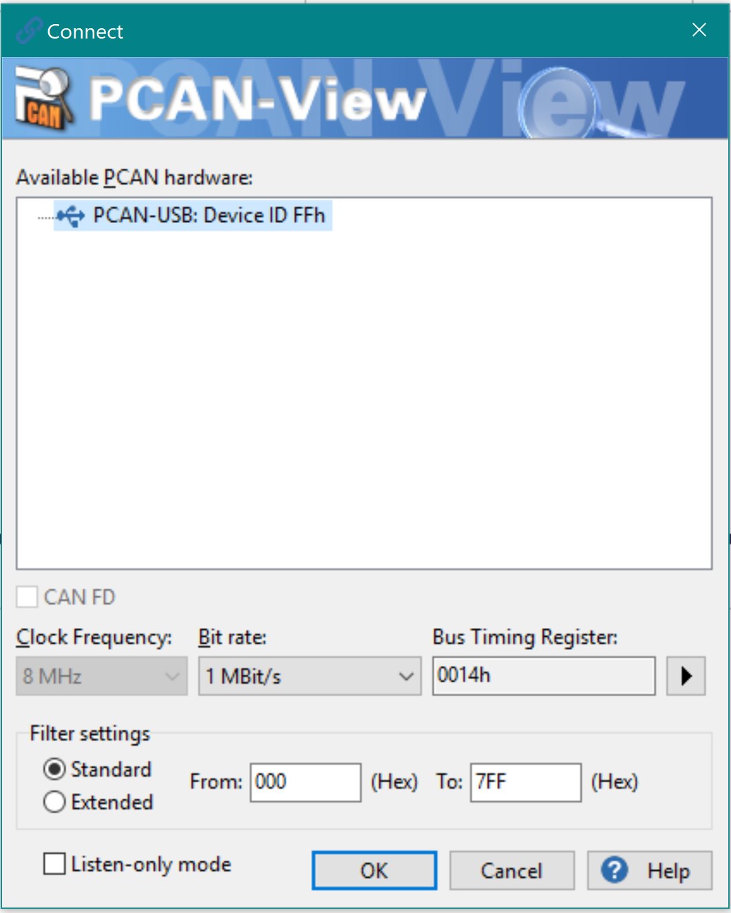
    One thing I see is that you are configuring Clock Frequency of PCAN as 8MHz. Module clock for MCAN on TDA4 is 80MHz.

    Below are my setting:

    The missing data issue was there with loopback too, I think we should focus on that. These issues seem to be same.

    I want to check if from the HW side things are ok, can you please try the below: (do this in the same run, don't power off)

    -1-

    ip link set can0 type can bitrate 1000000 dbitrate 5000000 fd on loopback on
    ip link set can0 up

    -2-

    Connect CCS, do NOT run GEL files, just attach to MCU2_1 (or any other core)
    Open Memory browser and check the register: MCAN0_CFG_MCAN_TXBC (0x027010C0) register and note the "value" of 15:2.

    -3-

    In the memory browser look at MCAN0 Message RAM: 0x02708000 + "value" << 2 (Value left shifted by 2)
    The above should be 0s.

    Now send the message using:
    cansend can0 113##2AAAAAAAA
    Again look at the same memory address, does it have the full message?

    Example of my setup:

    MCAN0_CFG_MCAN_TXBC = 0x01000908

    => value = 0x242

    => value << 2 = 0x908

    Address to be monitored before and after sending message:

    0x02708000 + 0x908 --> This is the first Tx buffer. Most likely the driver will use the 1st free buffer hence this should have the message.

    Regards,

    Karan

  • Hi Karan,

    I recently moved to SDK 7.1 and unfortunately, My Digital Spectrum XDS560v2 STM I can't connect to (MCU2_1) MAIN_Cortex_R5_0_1 core. This is the issue I am getting.

    The weird part is I can connect to DMSC and other CPU core but not MCU2_1. I tried to power off and power back on to the J7 board as well as JTAG but they didn't help. 

    Did you notice any such issues?

    Thanks,

    Satish

  • Hi Satish,

    This is because you must not be loading any firmware on the MCU2_1 core, as there is no firmware on the core - the bootloader doesn't take the core out of reset and you are not able to attach to the core from CCS.

    The intention is not to connect to MCU2_1 specifically, we want to any core from where we can view the MCAN controller's registers and message RAM.

    If you are able to connect to MCU2_0, that should also work for the experiment we are trying to do. Can you please try that?

    Regards,

    Karan  

  • Hi Karan,

    Unfortunately, I can't connect to any R Core using JTAG. 

    After reading this post : https://e2e.ti.com/support/processors/f/791/t/770144?CCS-AM6548-Can-not-connect-to-MCU-PULSAR-Cortex-R5-1 

    I connected to DMSC core and then ran GEL script to enable "split" mode for R5 core. At this point I was able to connect to MCU3_0 I can check the memory locations, however, at this point my A72 UART terminal is frozen and I can't send any command.

    By the way on MCU2_1 has an ethernet switch firmware loaded on my HW.

    Thanks,

    Satish

  • Hi Karan,

    Let's hold this issue for little bit. I recently found that SDK 7.1 bootloaders are not working on our board and I raised another question for it (here: https://e2e.ti.com/support/processors/f/791/t/977206 . Until I get SDK 7.1 working on our board it would be good to hold this issue. 

    I will return here after my board fully boots up with SDK 7.1.

    Thank you for the help.

    Satish

  • Hi Karan,

    I have returned to test CAN on my platform. We are sticking with SDK 7.0. Here is my findings

    1) I enabled the can0 interface with following of your command

    ip link set can0 type can bitrate 1000000 dbitrate 5000000 fd on loopback on
    ip link set can0 up

    2) I connected CPU core MCU2_0 in CCS and checked "0x027010C0" value and it was -
    MCAN0_CFG_MCAN_TXBC=0x01000908

    value = 0x242

    value << 2 = 0x908

    Those values are same like your setup.

    At this point I checked the value of "0x02708000 + 0x908" and it was 0


    3) Now I sent the can message i.e. "cansend can0 113##2AAAAAAAA"
    And again checked the value of "0x02708000 + 0x908" and it was like below. Of course, this is not matching with the value we just sent.

    One thing which I quite didn't understand, in your CCS snapshot why are you checking the value of "0x40500000 + 0x908"? 

    Anyway in my case the value of "0x40500000 + 0x908" is all 0x0.

    Thanks,

    Satish

  • Hi Satish,

    I think the CCS snapshot which I attached was when I was using the MCU MCAN instead on the MAIN MCAN. The MCU MCAN0 message ram starts from 0x40500000.

    Regards,

    Karan

  • Hi Karan,

    Any next steps which can help to find the root cause of this issue?

    Thanks,

    Satish

  • Hi Satish,

    Do you have the SBL brought up on your board? I'm thinking if we could try another application from the SDK to test the CAN interface?

    If not the only choice would be to modify the CAN driver to add some debug prints.

    Another helpful data point would be if you could dump and send me the MCAN Core registers (Table 12.4.4.5.2 of TRM) for the instance you are using - that would help me analyze if there are some errors in the transmission (This is less likely)

    Regards,

    Karan 

  • Do you have the SBL brought up on your board? I'm thinking if we could try another application from the SDK to test the CAN interface?

    >> By SBL, are you referring to tiboot3.bin? tiboot3.bin is the first bootloader I load while flahsing. Do you have any CAN application to test?

    If not the only choice would be to modify the CAN driver to add some debug prints.

    >> Could you point me the functions where you would like to see the debug prints in CAN driver and I will provide you logs.

  • Hi Satish,

    >> By SBL, are you referring to tiboot3.bin? tiboot3.bin is the first bootloader I load while flahsing. Do you have any CAN application to test?

    SBL is the Secondary boot loader, which we use mainly to boot RTOS applications. We have RTOS apps to test CAN in the SDK and hence was checking this.

    >> Could you point me the functions where you would like to see the debug prints in CAN driver and I will provide you logs.

    I will check this and comment.

    Regards,

    Karan

  • Hi Satish,

    I was reviewing the thread and I see a problem here with the CAN TX frame which is getting generated.

    From the memory browser snippet which you shared post the execution of "cansend can0 113##2AAAAAAAA"

    0x0270_8908 :: 0004_0000

    0x0270_890C :: 0081_0000

    0x0270_8910 :: 0000_0071

    Where as with the same cansend command I have:

    0x0270_8908 :: 044C_0000

    0x0270_890C :: 00A4_0000

    0x0270_8910 :: AAAA_AAAA

    So there is a problem with this buffer which will be transmitted. I tried to create the buffer (by writing directly to the memory from CCS) which you have and I see similar results as you.

    Can you try one experiment: (I am attaching a small video to help you with this)

    Using the same process which you used before, connect CCS and modify the addresses 0x0270_8908 to 0x0270_8910 as mentioned by me: (see above of see the snapshot I had sent earlier). This will create a valid message to be transmitted on the bus and then once you have that, trigger the message by writing to 0x1 to MCAN0_CFG_MCAN_TXBAR (0x0270_10D4).

    Video: /cfs-file/__key/communityserver-discussions-components-files/791/can_5F00_linux_5F00_transmission.zip

    Now, if this goes through then we know for sure that there is an issue with creating of the Tx buffer and no issue with HW.

    Regards,

    Karan

  • Hi Satish,

    -1-

    The driver code is under: linux_repo/drivers/net/can/m_can/.

    -2-

    I was reviewing the thread and I see a problem here with the CAN TX frame which is getting generated.

    From the memory browser snippet which you shared post the execution of "cansend can0 113##2AAAAAAAA"

    0x0270_8908 :: 0004_0000

    0x0270_890C :: 0081_0000

    0x0270_8910 :: 0000_0071

    Where as with the same cansend command I have:

    0x0270_8908 :: 044C_0000

    0x0270_890C :: 00A4_0000

    0x0270_8910 :: AAAA_AAAA

    So there is a problem with this buffer which will be transmitted. I tried to create the buffer (by writing directly to the memory from CCS) which you have and I see similar results as you.

    Can you try one experiment: (I am attaching a small video to help you with this)

    Using the same process which you used before, connect CCS and modify the addresses 0x0270_8908 to 0x0270_8910 as mentioned by me: (see above of see the snapshot I had sent earlier). This will create a valid message to be transmitted on the bus and then once you have that, trigger the message by writing to 0x1 to MCAN0_CFG_MCAN_TXBAR (0x0270_10D4).

    Video: /cfs-file/__key/communityserver-discussions-components-files/791/can_5F00_linux_5F00_transmission.zip

    Now, if this goes through then we know for sure that there is an issue with creating of the Tx buffer and no issue with HW.

    Regards,

    Karan

  • Hi Karan,

    Thank you for those instructions and for making a video for it.

    Around a month back I moved to SDK 7.1 and I tried the same instructions today. 

    root@j7-evm:~# ip link set can0 type can bitrate 1000000 dbitrate 5000000 fd on loopback on
    root@j7-evm:~# ip link set can0 up
    root@j7-evm:~# candump can0 &
    root@j7-evm:~# cansend can0 113##2AAAAAAAA
      can0  113  [04]  AA AA AA AA
      can0  113  [04]  AA AA AA AA
      
      
    root@j7-evm:~# cansend can0 123#DEADBEEF
      can0  123   [4]  DE AD BE EF
      can0  123   [4]  DE AD BE EF


    I do see that Message is coming fine now.  Since Loopback is working let me test this by connecting PCAN viewer and see if I can see similar data. I will test tomorrow and let you know.

    Thank you,

    Satish

  • Hi Satish,

    But I remember with these instructions you were only getting the CAN ID as the payload and the actual payload was not getting transmitted. (in Loopback as well as on PCAN)

    What changed after that?

    Regards,

    Karan

  • Hi Karan,

    Yes, you are right. from the Code point of view I have not changed anything from my side. It's just moving the SDK 7.1 fixed the issue. 

    I have a board with SDK 7.0 where I still see only ID is printing. Then I had some issues making SDK 7.1 working on our board so we  stayed with SDK 7.0.

    Few weeks (~1 Month) back I had help from TI to make SDK 7.1 work on our board and this is the first time I tested CAN loopback test on SDK 7.1.

    Thanks,

    Satish

  • Hi Karan,

    I have tested the CAN with my PCAN view. Here I don't see message from my Laptop to J7 and vice versa. 

    Does this command looks correct to you for sending CAN 2.0 frame from J7?

    ip link set can0 type can bitrate 1000000

    ip link set can0 up

    cansend can0 123#0011

    Thanks,

    Satish

  • Hi Satish,

    ip link set can0 type can bitrate 1000000

    ip link set can0 up

    cansend can0 123#0011

    These commands look ok.

    1. What settings do you have on the PCAN node side? All the CAN nodes on the bus should be configured the same, i.e. Classic CAN with 1Mbps bit rate here.

    I was able to verify on the EVM with these commands. PCAN settings as below:

    /resized-image/__size/320x240/__key/communityserver-discussions-components-files/791/pastedimage1619279875830v1.png

    2. Is your CAN transceiver connected to can0 configured correctly in the Device Tree?

    Regards,

    Karan

  • Hi Karan,

    I am using the following Setting on PCAN View. 

    Regarding 8MHz (My setting) vs 80 MHz (Your setting) - In my case, It doesn't allow me to select 80 MHz from the PCAN tool. The dropdown box is locked/disabled. 

    I called this PEAK tool provider (i.e. PHytools) , and spoke about selecting 80 MHz from the Dropdown box of "Clock Frequency". According to them, It is non-selectable. The NXP CAN transceiver contains in this tool uses 8 MHz and that's why it is selecting 8MHz. According to the Changing, the Clock frequency won't change the result and I should focus on the "Bit Rate". For Bitrate we have identical settings i.e. 1MBit for both of us.

    Another Experiment I did here is -

    I flashed SDK 7.0 image on my board and I do see that some part of the CAN 2.0 message (not all the data, just CAN ID) is received at PCAN view tool with exact PCAN settings i.e. 8MHz. See below - 

    However, as soon as I test it on SDK 7.1 I do see the entire CAN message in loopback but don't get any message at all on PCAN view. Would you know why I am receiving messages in SDK7.0 and what changed between SDK 7.0 and 7.1 in this regard?

    I have identical device tree changes with regards to can0 & can6 in SDK 7.0 & 7.1. I have also added GPIO hogging as you suggested earlier. Here it is - 

    	can0_faceplate_pins_default: can0_faceplate_pins_default {
    		pinctrl-single,pins = <
    			J721E_IOPAD(0x208, PIN_INPUT, 0) /* (W5) MCAN0_RX */
    			J721E_IOPAD(0x20c, PIN_OUTPUT, 0) /* (W6) MCAN0_TX */
    		>;
    	};
    
    
    	can6_faceplate_pins_default: can6_faceplate_pins_default {
    		pinctrl-single,pins = <
    			J721E_IOPAD(0x44, PIN_INPUT, 6) /* (AE24) PRG1_PRU0_GPO16.MCAN6_RX */
    			J721E_IOPAD(0x40, PIN_OUTPUT, 6) /* (AC24) PRG1_PRU0_GPO15.MCAN6_TX */
    		>;
    	};
    	
    	&main_mcan0 {
    	status = "okay";
    	pinctrl-names = "default";
    	pinctrl-0 = <&can0_faceplate_pins_default>;
    	can-transceiver {
    		max-bitrate = <5000000>;
    	};
    };
    
    &main_mcan6 {
    	status = "okay";
    	pinctrl-names = "default";
    	pinctrl-0 = <&can6_faceplate_pins_default>;
    	can-transceiver {
    		max-bitrate = <5000000>;
    	};
    };
    
    &main_gpio0 {
    	pinctrl-names = "default";
    	pinctrl-0 = <&gpio0_pins_default &debug_pins_default>;
    	power-domains = <&k3_pds 105 TI_SCI_PD_SHARED>;
    	status = "okay";
    
    	p84 {
    		gpio-hog;
    		gpios = <84 GPIO_ACTIVE_HIGH>;
    		output-low;
    		line-name = "MCAN0_STB";
    	};
    
    	p125 {
    		gpio-hog;
    		gpios = <125 GPIO_ACTIVE_HIGH>;
    		output-low;
    		line-name = "MCAN6_STB";
    	};
    };

    Thanks,

    Satish

  • Hi Satish,

    1. Can you confirm that the gpios? Can you replace gpio hog by using stb-gpios and en-gpios like https://git.ti.com/cgit/ti-linux-kernel/ti-linux-kernel/tree/arch/arm64/boot/dts/ti/k3-j721e-common-proc-board.dts?h=ti-linux-5.4.y#n964 ? Also, what transceiver is used on your board, is there no enable signal for it?

    You could probe the transceiver pins if that is easier.

    But if the transceiver is not enabled, you should get an error when transmitting, do you get any error when transmitting from board?

    2. There is no firmware on running on any core trying to configure the same GPIO or CAN module itself?

    Regards,

    Karan

  • Hi Karan,

    I have two MCAN i.e. can0 & can6. for the debug purpose, lets stick with one CAN i.e. can0. I have modified the device tree like below - 

    &main_mcan0 {
    	status = "okay";
    	pinctrl-names = "default";
    	pinctrl-0 = <&can0_faceplate_pins_default>;
    	stb-gpios = <&main_gpio0 84 GPIO_ACTIVE_HIGH>;
    	can-transceiver {
    		max-bitrate = <5000000>;
    	};
    };

    Part number of our transceiver is TCAN1044-Q1 . This is TI part. 

    While transmitting the CAN frame I don't see any error. The log is like below - 

    root@j7-evm:~# ip link set can0 type can bitrate 1000000
    root@j7-evm:~# 
    root@j7-evm:~# 
    root@j7-evm:~# ip link set can0 up
    [  345.280222] IPv6: ADDRCONF(NETDEV_CHANGE): can0: link becomes ready
    root@j7-evm:~# cansend can0 123#0011
    [  358.546489] can: controller area network core (rev 20170425 abi 9)
    [  358.552737] NET: Registered protocol family 29
    [  358.559931] can: raw protocol (rev 20170425)
    root@j7-evm:~# 


    Yeah, there is no firmware is loaded in the other core. A72 is the only core where Linux is booting & configuring this GPIO.

    Thanks,

    Satish

  • Hi Satish,

    Apologies for a delay here, I need to look though this. I will get back to you in a couple of days.

    Regards,

    Karan

  • Hi Satish,

    For my understanding, to reiterate, internal loopback with SDK7.1 works for you but external communication with PCAN tool is not working. Please let me know if there was another development after that.

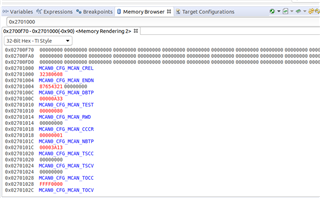
    Coming back to the topic, can you please check the MCAN0's core registers? These are from 0x0270_1000 to 0x0270_10F8.

    As before connect CCS, send a message from A72 using "cansend can0 123#0011". Open the memory browser and click on Continuous Refresh button (see below), this is because the CAN core will try to retransmit messages (due to DAR=0) and hence the values of some registers may change. See if there are any changing values, changed values will appear in red colour.

    Send me the values of these registers. Screen capture from CCS memory browser will work.

    Regards,

    Karan

  • Hi Karan,

    Are you available for a few min to take a look at my setup? I thought it would be easy to debug this if we quickly take a look at this issue to live for a few minutes.

    Thanks,

    Satish

  • Hi Satish,

    I will schedule a meeting sometime this week.

    Regards,

    Karan

  • Debug call summary:

    1. The can0 interface being being created is corresponding to the MCU MCAN0 instead of MCAN0. can2 will correspond to the MCAN0.

    Check this by running ls -la /sys/class/net/can*/device

    2. The STB GPIOs being requested by the driver are already hogged in the DTS. This will cause an error in the driver probe and the MCAN0 device will not be registered. See dmesg for more information on this.

    dmesg | grep can

    Suggested steps:

    Remove the stb gpios field from the MCAN0 and MCAN6 nodes and use that device tree. Check lookback first and then check external communication.

    Make sure that the MCAN0 and MCAN6 devices are being registered and the transceiver configuration is taking place.

    Regards,

    Karan

  • Satish,

    Additional thing here would also be to check what state are you driving the STB pin of the transceiver, I saw that you have re-used from my patch on the EVM, so check your schematics on how that gpio0_84 is connected. You want to make the STB pin low for your transceiver.

    Alternatively, if things don't work with what you currently have in the gpio-hog, then change the GPIO_ACTIVE_HIGH to GPIO_ACTIVE_LOW.

    Regards,

    Karan

  • Hi Karan,

    Thank you for the Debug session. I removed the gpio hog part from my device tree and now I see all four CAN probe in dmesg. 

    root@j7-evm:~# dmesg | grep can
    [    3.720273] davinci_mdio 46000f00.mdio: no live phy, scanning all
    [    4.196886] davinci_mdio 46000f00.mdio: no live phy, scanning all
    [    4.315527] pinctrl-single 4301c000.pinmux: pin PIN10 already requested by 47040000.spi; cannot claim for 2b30000.mcasp
    [    7.624381] m_can_platform 40528000.can: m_can device registered (irq=15, version=32)
    [    7.869878] m_can_platform 40568000.can: m_can device registered (irq=17, version=32)
    [    8.455019] m_can_platform 2701000.can: m_can device registered (irq=50, version=32)
    [    8.761381] m_can_platform 2761000.can: m_can device registered (irq=52, version=32)
    [  314.053063] IPv6: ADDRCONF(NETDEV_CHANGE): can0: link becomes ready
    [  321.014441] can: controller area network core (rev 20170425 abi 9)
    [  321.027822] can: raw protocol (rev 20170425)
    root@j7-evm:~# 

    However, I see that "can0" is still linked to MCU MCAN. Loopback works fine however I still don't see message on my Laptop (connected via PEAK). chainging gpio settings from GPIO_ACTIVE_HIGH to GPIO_ACTIVE_LOW didn't help too.

    ls -la /sys/class/net/can*/device
    lrwxrwxrwx 1 root root 0 Jun 14 22:34 /sys/class/net/can0/device -> ../../../40528000.can
    lrwxrwxrwx 1 root root 0 Jun 14 22:34 /sys/class/net/can1/device -> ../../../40568000.can
    lrwxrwxrwx 1 root root 0 Jun 14 22:34 /sys/class/net/can2/device -> ../../../2701000.can
    lrwxrwxrwx 1 root root 0 Jun 14 22:34 /sys/class/net/can3/device -> ../../../2761000.can

    Something is weird - In my device tree I linked CAN0 to "main_mcan0: can@2701000" but it is pointing to "40528000". I did my search in the device tree but didn't find any assignment to "40528000". 

    Thanks,

    Satish

  • Hi Satish,

    The external communication you tried was with the can0 or can2?

    Regards,

    Karan

  • Hi Karan,

    Initially, I have tried can0 (which is wrong). However, after your reply, I tried with can2 and still don't see the CAN message on my PC. 

    I will try to capture the CCS register log and send you today. Do you think we should look for any other logs?

    Thanks,

    Satish

  • Hi Satish,

    When you try can2, are you taking care of enabling the transceiver? Did you check the connections to the transceiver and also how do you enable the transceiver can you please post that code?

    Regards

    Karan

  • Hi Karan,

    I have double verified my connection with the transceiver and they look fine. When I issue these commands 

    ip link set can2 type can bitrate 1000000
    ip link set can2 up
    cansend can2 123#DEADBEEF

    I see the following value changed on CCS memory browser (Red text).

    My device tree settings look like this -

    &main_mcan0 {
    	status = "okay";
    	pinctrl-names = "default";
    	pinctrl-0 = <&can0_faceplate_pins_default>;
    	stb-gpios = <&main_gpio0 84 GPIO_ACTIVE_HIGH>;
    	can-transceiver {
    		max-bitrate = <5000000>;
    	};
    };

    Thanks,

    Satish

  • Hi Karan,

    I guess I missed asking, does that CCS snapshot make sense to you?

    Edit: Not sure what happened but my previous response turned green somehow.

    Thanks,

    Satish 

  • Hi Satish,

    I guess I missed asking, does that CCS snapshot make sense to you?

    The PSR register will help understand if there were any protocol errors, can you check that?

    Regards

    Karan

  • Hi Karan,

    Are you referring to this register?

    MCAN0_CFG_MCAN_PSR - 0x02701044

    - Satish

  • Hi Satish,

    Yes this is the correct register, you can read that and see if there are any protocol errors from the CAN controller. Look at the LEC and DLEC fields.

    Regards

    Karan