Other Parts Discussed in Thread: OMAPL138
Dear all,
We have purchased a LCDK6487 to work with it.
I have installed CCS and SDK and all examples.
I have just started to work with “GPIO_LedBlink_lcdkOMAPL138_c674xTestProject.” I am able to Build, debug and run.
As an exercise, I would like also move another led in the board. LCDK6487 board has 4 leds:
D4 on pin GPIO6[13],
D5 on pin GPIO6[12]
D6, on pin GPIO2-12
D7 on pin GPIO0-9.
The example is moving D4 and D5, which are equivalent in the main.c file to USER_LED0 and USER_LED1:
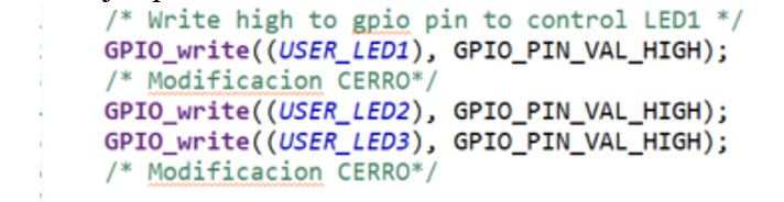
/* Toggle LED1 */
GPIO_toggle(USER_LED1);
On file board_cfg.h lines 70-74, there are the following declaration:
/* GPIO pin and port numbers for on-board LED */
#define GPIO_LED0_PIN_NUM (108U)
#define GPIO_LED0_PORT_NUM (0U)
#define GPIO_LED1_PIN_NUM (109U)
#define GPIO_LED1_PORT_NUM (0U)
I dont see in any file the relation between the above declaration and USER_LED1 and USER_LED0.
My questions are very simple:
How can I control other leds (D6 and D7) in the board?
Which are the steps to follow? Which files should I modified?
Is there any document which explain the process and all the things to do?
Sorry if the questions are so simple but I have just starting to work with DSPs and I get lost in the gap oHW/software.
Thanks in advance,
Joaquin.