This thread has been locked.

If you have a related question, please click the "Ask a related question" button in the top right corner. The newly created question will be automatically linked to this question.

AM3358: Display issue

Part Number: AM3358

Hi,

SDK: PSDK 06.03.00.106

Customized board boots from SD card, display screen can show picture A successfully.

_48659C67_3.png (507×341)

                                             picture A


When using the command cat logo-7.bmp> /dev/fb0, It should show figure b, but it actually shows figure c.

_48659C67_.png (221×150)

                     figure B

_48659C67_2.png (523×347)

                                                    figure C

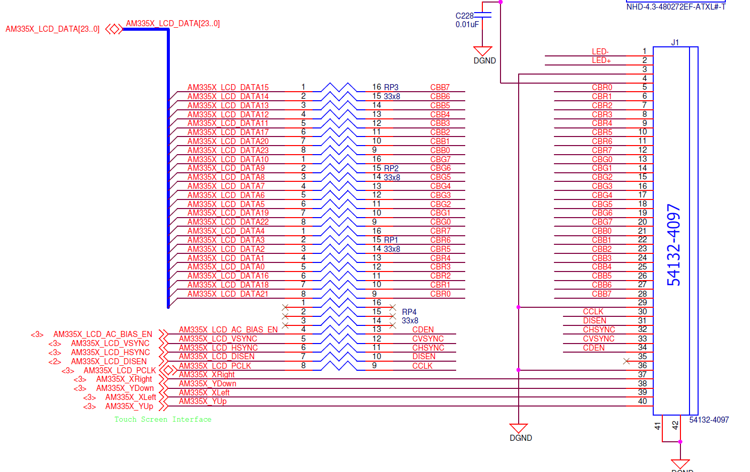
Below is the configuration:

panel {

compatible = "ti,tilcdc,panel";
pinctrl-names = "default", "sleep";
pinctrl-0 = <&lcd_pins_default>;
pinctrl-1 = <&lcd_pins_sleep>;
status = "okay";
panel-info {
ac-bias = <255>;
ac-bias-intrpt = <0>;
dma-burst-sz = <16>;
bpp = <32>;
fdd = <0x80>;
sync-edge = <0>;
sync-ctrl = <1>;
raster-order = <0>;
fifo-th = <0>;
};
display-timings {
800x480 {
hactive = <800>;
vactive = <480>;
hback-porch = <88>;
hfront-porch = <40>;
hsync-len = <128>;
vback-porch = <32>;
vfront-porch = <11>;
vsync-len = <2>;
clock-frequency = <33200000>;
hsync-active = <0>;
vsync-active = <0>;
};
};

Please help check.

  • Hello,

    The display configuration is correct but we do not support fbdev. I have seen similar issues being reported where the fbdev does not clear the previous framebuffer. However, the Linux community has stopped maintaining the fbdev framework.

    I am wondering if you could please share more information about your use case so we could suggest other alternatives. 

    Regards,
    Krunal

  • The purpose of this is to make the screen display the specified picture to verify the quality of the screen (no QT).

    besides,When I use 32-bit BMP, the image is reversed and partially offset, and  error  “cat: write error: no space left on device is reported”

    It should look like this:

    but the true is :

  • Hello,

    With regards to the color swap, please refer to the silicon errata (3.1.1 LCD: Color Assignments of LCD_DATA Terminals). The blue and red color assignments to the LCD data pins are reversed when operating in RGB888 (24bpp) mode compared to RGB565 (16bpp) mode. I am not sure about your configuration but for one of our boards we added a special entry in the dts file to compensate for the above errata. 

    I would also recommend running kmstest and it shows various color bars on the display. The first three color bars should be red, green and blue. 

    Regards,
    Krunal

  • No,the problem is the image be reversed and White balance turns red

    like this  

    Can you provide a way to display the specified picture without QT.

  • and the picture is shifted to one side

  • Hello,

    Another alternative would be using gstreamer and I use the following pipeline for displaying an image:

    gst-launch-1.0 filesrc location=/home/root/fb.png ! pngdec ! videoconvert ! imagefreeze ! waylandsink

    Also, let's try to capture the framebuffer using the following commands:
    1. Launch your application
    2. Upon successful launch, suspend the application using the "Ctrl + z" 
    3. Execute the following command: "cat /sys/kernel/debug/dri/0/framebuffer"
    4. It will list all the framebuffers and for each buffer, capture the paddr and size
    5. Capture the raw data using the command: rwmem -R paddr+size > fb.data (rwmem binary attached below)
    6. Copy the data into your Linux machine and run the command: convert -depth 8 -size 800x480 -color-matrix "0 0 1 0 1 0 1 0 0" -alpha deactivate rgba:fb.data fb.png (Change the width and height based on your setup)

    Please try the above steps for each framebuffer and share the output images. 

    Regards,
    Krunal

    https://e2e.ti.com/cfs-file/__key/communityserver-discussions-components-files/791/rwmem

  • hello

    I try to do follow your advice ,but get the problem.

    root@am335x-evm:/boot# cat 32.bmp >/dev/fb0
    cat: write error: No space left on device
    root@am335x-evm:/boot# cat /sys/kernel/debug/dri/0/framebuffer
    framebuffer[34]:
    allocated by = [fbcon]
    refcount=2
    format=XR24 little-endian (0x34325258)
    modifier=0x0
    size=800x480
    layers:
    size[0]=800x480
    pitch[0]=3200
    offset[0]=0
    obj[0]:
    name=0
    refcount=3
    start=00010000
    size=1536000
    imported=no
    paddr=0x9d100000
    vaddr=3f1894a5
    root@am335x-evm:/boot# rwmem -R 0x9d100000+1536000>fb.data
    /oe/bld/build-CORTEX_1/arago-tmp-external-arm-toolchain/work/armv7at2hf-neon-linux-gnueabi/rwmem/1.2+gitAUTOINC+cc296c5366_4b10c65405_9a19306fbf-r0/git/librwmem/mmaptarget.cpp:177: void* MMapTarget::maddr(uint64_t) const:
    address below map range
    Aborted (core dumped)
    root@am335x-evm:/boot#

    then copy fb.data to Ubutun

    45@ubuntu:/media/45/rootfs/boot$ sudo convert -depth 8 -size 800x480 -color-matrix "0 0 1 0 1 0 1 0 0" -alpha deactivate rgba:fb.data 654.png
    convert: unexpected end-of-file `fb.data': Invalid parameter @ error/rgb.c/ReadRGBImage/237.

    when i use the gst-launch-1.0,


    root@am335x-evm:/boot# gst-launch-1.0 filesrc location=/boot/654.png ! pngdec ! videoconvert ! imagefreeze ! waylandsink
    Setting pipeline to PAUSED ...
    ERROR: Pipeline doesn't want to pause.
    WARNING: from element /GstPipeline:pipeline0/GstWaylandSink:waylandsink0: Could not initialise Wayland output
    Additional debug info:
    ../../../gst-plugins-bad-1.14.4/ext/wayland/gstwaylandsink.c(333): gst_wayland_sink_find_display (): /GstPipeline:pipeline0/GstWaylandSink:waylandsink0:
    Failed to create GstWlDisplay: 'Failed to connect to the wayland display '(default)''
    Setting pipeline to NULL ...
    Freeing pipeline ..

  • Hello,

    Please do not use the default rwmem command and use the one I attached in my previous thread. Also, since the rwmem binary exists in the /usr/bin folder, I would recommend using relative path to launch the binary (./rwmem). 

    Do you have weston enabled on your board? if not, please try the following pipeline "gst-launch-1.0 filesrc location=/boot/654.png ! pngdec ! videoconvert ! imagefreeze ! kmssink driver-name=tilcdc

    Regards,
    Krunal

  • Hello

    thanks,I can  displaying an image by the pipeline 

    ------------------------------------------------------------------------------------------------------------------------------------------

    I plan to show pictures in another LVDS, but part of the picture turns green。

    when I use the kmstest, The colored bands in the image are not shown properly, and I can see that each ribbon is made up of long strips of different colors. The border that should have shown blue shows purple, and the border that should have shown red shows green.

    LVDS parameters

    Tv=500

    Tvd=480

    Tvb=20

    Th=992

    Thd=800

    Thb=192

    clock=29.5MHz
    the dts

    panel-info {
    ac-bias = <255>;
    ac-bias-intrpt = <0>;
    dma-burst-sz = <16>;
    bpp = <32>;
    fdd = <0x80>;
    sync-edge = <0>;
    sync-ctrl = <1>;
    raster-order = <0>;
    fifo-th = <0>;
    };
    display-timings {
    800x480 {
    hactive = <800>;
    vactive = <480>;
    hback-porch = <100>;
    hfront-porch = <90>;
    hsync-len = <2>;
    vback-porch = <10>;
    vfront-porch = <8>;
    vsync-len = <2>;
    clock-frequency = <29500000>;
    hsync-active = <0>;
    vsync-active = <0>;
    };
    };

    AM33XX_IOPAD(0x8a0, PIN_OUTPUT | MUX_MODE0)
    AM33XX_IOPAD(0x8a4, PIN_OUTPUT | MUX_MODE0)
    AM33XX_IOPAD(0x8a8, PIN_OUTPUT | MUX_MODE0)
    AM33XX_IOPAD(0x8ac, PIN_OUTPUT | MUX_MODE0)
    AM33XX_IOPAD(0x8b0, PIN_OUTPUT | MUX_MODE0)
    AM33XX_IOPAD(0x8b4, PIN_OUTPUT | MUX_MODE0)
    AM33XX_IOPAD(0x8b8, PIN_OUTPUT | MUX_MODE0)
    AM33XX_IOPAD(0x8bc, PIN_OUTPUT | MUX_MODE0)
    AM33XX_IOPAD(0x8c0, PIN_OUTPUT | MUX_MODE0)
    AM33XX_IOPAD(0x8c4, PIN_OUTPUT | MUX_MODE0)
    AM33XX_IOPAD(0x8c8, PIN_OUTPUT | MUX_MODE0)
    AM33XX_IOPAD(0x8cc, PIN_OUTPUT | MUX_MODE0)
    AM33XX_IOPAD(0x8d0, PIN_OUTPUT | MUX_MODE0)
    AM33XX_IOPAD(0x8d4, PIN_OUTPUT | MUX_MODE0)
    AM33XX_IOPAD(0x8d8, PIN_OUTPUT | MUX_MODE0)
    AM33XX_IOPAD(0x8dc, PIN_OUTPUT | MUX_MODE0)
    AM33XX_IOPAD(0x83c, PIN_OUTPUT | MUX_MODE1)
    AM33XX_IOPAD(0x838, PIN_OUTPUT | MUX_MODE1)
    AM33XX_IOPAD(0x834, PIN_OUTPUT | MUX_MODE1)
    AM33XX_IOPAD(0x830, PIN_OUTPUT | MUX_MODE1)
    AM33XX_IOPAD(0x82c, PIN_OUTPUT | MUX_MODE1)
    AM33XX_IOPAD(0x828, PIN_OUTPUT | MUX_MODE1)
    AM33XX_IOPAD(0x824, PIN_OUTPUT | MUX_MODE1)
    AM33XX_IOPAD(0x820, PIN_OUTPUT | MUX_MODE1)
    AM33XX_IOPAD(0x8e0, PIN_OUTPUT | MUX_MODE0)
    AM33XX_IOPAD(0x8e4, PIN_OUTPUT | MUX_MODE0)
    AM33XX_IOPAD(0x8e8, PIN_OUTPUT | MUX_MODE0)
    AM33XX_IOPAD(0x8ec, PIN_OUTPUT | MUX_MODE0)

    ------------------------------------------------------------------------------------------------------------------------------------------

    I  use the  rwmem command  ,but  

    root@am335x-evm:/usr/bin# ./rwmem

    -sh: ./rwmem: cannot execute binary file: Exec format error

    root@am335x-evm:/usr/bin# rwmem -R 0x9d100000+1536000 > fb.data

    -sh: /usr/bin/rwmem: cannot execute binary file: Exec format error

    I check the rwmem

    file rwmem

    rwmem: ELF 32-bit LSB executable, ARM, version 1 (SYSV), corrupted program header size, corrupted section header size

  • thanks,I can  displaying an image by the pipeline 

    Is the image still distorted or it shows the correct output? 

     I plan to show pictures in another LVDS 

    Could you please share more information about your setup? I am not sure if I understand what you meant by another LVDS.

     when I use the kmstest, The colored bands in the image are not shown properly, and I can see that each ribbon is made up of long strips of different colors. The border that should have shown blue shows purple, and the border that should have shown red shows green. 

    Please share the picture of the output image. Also, if possible, more information about your LCD HW connection. 

     rwmem: ELF 32-bit LSB executable, ARM, version 1 (SYSV), corrupted program header size, corrupted section header size 

    It seems like the image file that I uploaded got corrupted and I have attached a tar ball.

    binary.tar.gz

    Regards,

    Krunal

  • 1. It can output normally
    2. I have another board, other circuits are basically the same, but in the display part, I use sn65lvds93adggr with another screen. The circuit is recommended by sn65lvds93adggr.

    3. The output image of kmstest is as follows

    4.Tomorrow I'll try to see if I can use rwmem

  • Hello,

    Please correct me if I am wrong but it seems like you have 2 different displays. The first display works and the output image is as expected. However, the second display has issues based on the above kmstest output. How does the output of gstreamer look like for the non-functional display?

    With regards to the HW connection, both displays are 24 bit and do they come from different vendor? 

    Regards,

    Krunal

  • use

    gst-launch-1.0 filesrc location = / boot / 09.png!pngdec!videoconvert!imagefreeze!kmssink driver-name = tilcdc

    The original picture is

    and the display show 

    the first display is 16bit and in RGB mod,the second display is 24bit and in LVDS mod.They are from different manufacturers.


  • Hello,

    As mentioned in our silicon errata, the blue and red color assignments to the LCD data pins are reversed when operating in RGB888 (24bpp) mode compared to RGB565 (16bpp) mode. I am wondering if you have added the property "blue-and-red-wiring = "crossed"" in your lcdc node. We have done something similar on our dts configuration: https://git.ti.com/cgit/ti-linux-kernel/ti-linux-kernel/tree/arch/arm/boot/dts/am335x-evmsk.dts?h=ti-linux-4.19.y#n756

    Regards,
    Krunal

  • I added but it makes things worse.In addition, the interface that displays please wait (should be black) turns blue

  • Hello.

    Is the LVDS hardware connection (lcd0-d0 ~ lcd22-d22, lcd23-d27) correct?

  • Hello,

    Before we check the HW connection and LCD configuration, could you please run the rwmem? It will tell us if the image going to LCD is corrupted or not.

    Regards,
    Krunal

  • thanks.

    the second board is sure that HW connection is wrong.

  • Hello,

    I am checking internally and I will get back to you.

    Regards,
    Krunal

  • Hello,

    Here is a reference of how we connect the 24bit LCD to our SoC:

    I am wondering if it is possible for you to configure your LCD as shown above. Also, if you plan to use the above configuration, please add the following to your software ""blue-and-red-wiring = "crossed"".

    Regards,

    Krunal

  • I will try that.

    I've added " blue-and-red-wiring = "crossed" " to  am33xx.dtsi ,Do I need to add it to am335x.dts?

  • Hello,

    I recommend adding it to the dts file and only add the above statement after modifying your board. Also, please make sure the timing values for the LCD match the panel datasheet.

    Regards,
    Krunal