This thread has been locked.

If you have a related question, please click the "Ask a related question" button in the top right corner. The newly created question will be automatically linked to this question.

J721EXSOMXEVM: Main UART to WAKEUP uart bridge

Part Number: J721EXSOMXEVM
Other Parts Discussed in Thread: SYSCONFIG

Hello,

How can we bridge Main Domain UART (i.e. UART6) with WAKEUP domain UART from A72 w/ Linux? 

Thanks,

Satish

  • Hi Satish,

    Can you explain more on what do you mean by bridging? Do you want to route the MAIN UARTs prints to WKUP UART?

    Regards,

    Karan

  • Hi Karan,

    We have a UART6 where there is an SoC sending the logs in it. We want to access this log and send some commands from our Teraterm terminal in PC. We are exploring options to establish bidirectional communication between UART6 to WKUP UART. Our setup is Like This -

    PC (Tera term terminal) <----------> WKUP UART <-------------> UART 6 <------------> SoC (not J7) 

    In our case, WKUP UART is pretty much unused at the moment. if we can establish a bidirectional communication/bridge between UART6 to WKUP UART that would be great. 

    Thanks,

    Satish

  • Hi Satish,

    So essentially you want to do communication between another SoC and J7 using UART as the trigger?

    Regards,

    Karan

  • Yes UART6 is the communication medium between another SoC and J7.

    However UART6 interface is not accessible externally from our FTDI UART chip and that's the reason we are trying to establish bidirectional communication between UART6 & WKUP UART so we can reach to UART6 via WKUP UART.

  • Hi Satish,

    I have started the discussion with the wider team on if something like this is feasible and if yes, how can that be achieved. 

    I will try to get back by end of this week.

    Meanwhile,

    PC (Tera term terminal) <----------> TDA4's  WKUP UART <-------------> TDA4's UART 6 <------------> SoC (not J7) 

    1. Is the link TDA4's UART 6 <------------> SoC (not J7)  also hard wired, as in this also can not change? The other SoC is hard wired to TDA4's UART6?

    2. Was this a design choice or somehow got missed?

    Regards,

    Karan

  • However UART6 interface is not accessible externally from our FTDI UART chip

    Also, can you please explain more on what do you mean by this?

    Regards,

    Karan

  • Hi Karan,

    UART6 & other SoC is hardwired and it can not be changed. Also, it was a part of hardware design planning.

    We have an FTDI chip that emulates Main Domain UART (UART7), WKUP UART & MCU UART. Since UART6 is connected to another SoC we can not access it directly via the Teraterm terminal from PC. That's the reason we are trying to establish communication between UART6 & WKUP UART. So when we connect to WKUP UART we can send/receive messages from other SoC over UART6.

  • Hi Satish,

    Will it be possible for you to read from WKUP UART to a buffer (buff) in some memory (on J7) and then write that buff to UART6? There will be processors cycles involved here as you have to do a copy and it would not be WKUP UART to UART 6 direct routing.

    Regards,

    Karan

  • Hi Karan,

    I am trying to read the UART6 data from J7 terminal.

    I learned that the baud rate of UART6 has to be 230400 which I set using "stty -F /dev/ttyS8 230400" command. After setting the baud rate I am trying to read data but I still don't see any data.

    Question is:

    1) Default baud rate in SDK is set to 115200 for UART6, How can I change the baud rate in device tree to set it to 230400?

    2) I noticed in "k3-j721e-main.dtsi" that clock frequence is set to "clock-frequency = <48000000>;", Does this need change to achieve the higher baud rate (i.e. 230400)?

    3) Is there a way to get the logs for the Hardware handshake (mainly RTS & CTS lines)? 

    Thanks,

    Satish

  • Karan,

    Adding one more question here:

    4) What changes are required to enable RTS & CST support in Device tree?

    Thank your for your help here.

    Satish

  • Hi Satish,

    Default baud rate in SDK is set to 115200 for UART6, How can I change the baud rate in device tree to set it to 230400?

    2) I noticed in "k3-j721e-main.dtsi" that clock frequence is set to "clock-frequency = <48000000>;", Does this need change to achieve the higher baud rate (i.e. 230400)?

    The options for clock are 48 or 96MHz, I don't think you would need to change that, but I will confirm that.

    Just try changing the current-speed from 115200 to 230400.

    On question 3 and 4 I have asked another engineer to respond.

    Regards,

    Karan

  • Hi Karan,

    Actually I already I tried changing "current-speed" in device tree (i.e. both in uboot & Kernel) under " main_uart6: serial@2860000" of k3-j721e-main.dtsi as well as "&uart6" of k3-j721e-common-proc-board.dts file. These changes didn't help. UART6 still comes up as 9600 baud rate when OS boots up.

    This is how I checked the baud rate (ttyS8 is mapped to uart6) 

    root@j7-evm:~# stty < /dev/ttyS8
    speed 9600 baud; line = 0;
    -brkint -imaxbel
    root@j7-evm:~# 
    

    k3-j721e-common-proc-board.dts

    	main_uart6: serial@2860000 {
    		compatible = "ti,j721e-uart", "ti,am654-uart";
    		reg = <0x00 0x02860000 0x00 0x100>;
    		reg-shift = <2>;
    		reg-io-width = <4>;
    		interrupts = <GIC_SPI 198 IRQ_TYPE_LEVEL_HIGH>;
    		clock-frequency = <48000000>;
    		current-speed = <230400>;
    		power-domains = <&k3_pds 283 TI_SCI_PD_EXCLUSIVE>;
    		clocks = <&k3_clks 283 0>;
    		clock-names = "fclk";
    	};

    k3-j721e-main.dtsi 

    &main_uart6 {
    	pinctrl-names = "default";
    	pinctrl-0 = <&uart6_switch_mgmt_pins_default>;
    	current-speed = <230400>;
    	power-domains = <&k3_pds 283 TI_SCI_PD_SHARED>;
    	status = "okay";
    };

    Thanks,

    Satish

  • What changes are required to enable RTS & CST support in Device tree?

    Example UART6: https://dev.ti.com/sysconfig/?fromPinmux=true#/config/?args=--device%20J721E_DRA829_TDA4VM_AM752x%20--part%20Default%20--package%20ALF%20--theme%20light

    &main_pmx0 {
    myuart1_pins_default: myuart1_pins_default {
    pinctrl-single,pins = <
    J721E_IOPAD(0x210, PIN_INPUT, 1) /* (W3) MCAN1_RX.UART6_CTSn */
    J721E_IOPAD(0x214, PIN_OUTPUT, 1) /* (V4) MCAN1_TX.UART6_RTSn */
    J721E_IOPAD(0x218, PIN_INPUT, 8) /* (W2) I3C0_SCL.UART6_RXD */
    J721E_IOPAD(0x21c, PIN_OUTPUT, 8) /* (W1) I3C0_SDA.UART6_TXD */
    >;
    };

    Pasting the output of sysconfig tool above for MAIN_UART6 pin config with RTS & CTS.

    Is there a way to get the logs for the Hardware handshake (mainly RTS & CTS lines)? 

    Are you asking for some sort of protocol analyzer? I am not sure of that.

    - Keerthy

  • 2) I noticed in "k3-j721e-main.dtsi" that clock frequence is set to "clock-frequency = <48000000>;", Does this need change to achieve the higher baud rate (i.e. 230400)?

    As Karan rightly mentioned no need to change that functional clock frequency for changing Baud.

    - Keerthy

  • Hi Keerthy,

    Thank you for those answers. Not sure why but I didn't get any notification or notification email on this post from E2E website.

    Could you please also let me know how can I change the baud rate of UART6 ?

    I changed  " current-speed = <115200>;" to " current-speed = <230400>;" in k3-j721e-main.dtsi. I made this change both in the bootloader and kernel. After making this change I flashed bootloader and kernel and I see the baud rate of UART6 (ttyS8) as 9600

  • Hi Satish,

    I checked with our UART expert:

    It seems current-speed  is not really used by driver so you can ignore that.

    And please give us the dump of this command:
    'k3conf dump clock 283'

    One thing we suspect is HW flow control is disabled by default with TDA4. So we need to explicitly enable
    by using stty: https://tldp.org/HOWTO/Modem-HOWTO-7.html

    We need to make sure that cts/rts pin muxing is proper in DT. I believe you have already taken care of that.

    stty -F /dev/ttyS8 -a

    Can you please give us the output of this command?


    Regards,
    Keerthy

  • Hi Keerthy, 

    Here is the output of 'k3conf dump clock 283'

    root@j7-evm:~# k3conf dump clock 283
    |--------------------------------------------------------------------------------|
    | VERSION INFO                                                                   |
    |--------------------------------------------------------------------------------|
    | K3CONF | (version v0.1-34-g1ff0c4f built Tue Mar 30 04:58:11 UTC 2021)         |
    | SoC    | J721E SR1.0                                                           |
    | SYSFW  | ABI: 3.1 (firmware version 0x0014 '20.8.5--v2020.08b (Terrific Lla)') |
    |--------------------------------------------------------------------------------|
    
    |--------------------------------------------------------------------------------|
    | Device ID | Clock ID | Clock Name          | Status          | Clock Frequency |
    |--------------------------------------------------------------------------------|
    |   283     |     0    | DEV_UART6_FCLK_CLK  | CLK_STATE_READY | 48000000        |
    |   283     |     1    | DEV_UART6_VBUSP_CLK | CLK_STATE_READY | 125000000       |
    |--------------------------------------------------------------------------------|
    
    root@j7-evm:~# 
    

    Here is the output of stty -F /dev/ttyS8 -a

    root@j7-evm:~# stty -F /dev/ttyS8 -a
    speed 9600 baud; rows 0; columns 0; line = 0;
    intr = ^C; quit = ^\; erase = ^?; kill = ^U; eof = ^D; eol = <undef>; eol2 = <undef>; swtch = <undef>; start = ^Q; stop = ^S; susp = ^Z; rprnt = ^R; werase = ^W; lnext = ^V; discard = ^O; min = 1; time = 0;
    -parenb -parodd -cmspar cs8 hupcl -cstopb cread clocal -crtscts
    -ignbrk -brkint -ignpar -parmrk -inpck -istrip -inlcr -igncr icrnl ixon -ixoff -iuclc -ixany -imaxbel -iutf8
    opost -olcuc -ocrnl onlcr -onocr -onlret -ofill -ofdel nl0 cr0 tab0 bs0 vt0 ff0
    isig icanon iexten echo echoe echok -echonl -noflsh -xcase -tostop -echoprt echoctl echoke -flusho -extproc

    after enabling cts/rts using "stty -F /dev/ttyS8 crtscts" output of "stty -F /dev/ttyS8 -a" is

    root@j7-evm:~# stty -F /dev/ttyS8 -a
    speed 9600 baud; rows 0; columns 0; line = 0;
    intr = ^C; quit = ^\; erase = ^?; kill = ^U; eof = ^D; eol = <undef>; eol2 = <undef>; swtch = <undef>; start = ^Q; stop = ^S; susp = ^Z; rprnt = ^R; werase = ^W; lnext = ^V; discard = ^O; min = 1; time = 0;
    -parenb -parodd -cmspar cs8 hupcl -cstopb cread clocal crtscts
    -ignbrk -brkint -ignpar -parmrk -inpck -istrip -inlcr -igncr icrnl ixon -ixoff -iuclc -ixany -imaxbel -iutf8
    opost -olcuc -ocrnl onlcr -onocr -onlret -ofill -ofdel nl0 cr0 tab0 bs0 vt0 ff0
    isig icanon iexten echo echoe echok -echonl -noflsh -xcase -tostop -echoprt echoctl echoke -flusho -extproc

    On Pinmuxing - Yes I have RTS & CST lines enabled in DT. This is the code I have 

    	uart6_switch_mgmt_pins_default: uart6_switch_mgmt_pins_default {
    		pinctrl-single,pins = <
    			J721E_IOPAD(0x210, PIN_INPUT, 1) /* (W3) MCAN1_RX.UART6_CTSn */
    			J721E_IOPAD(0x214, PIN_OUTPUT, 1) /* (V4) MCAN1_TX.UART6_RTSn */
    			J721E_IOPAD(0x218, PIN_INPUT, 8) /* (W2) I3C0_SCL.UART6_RXD */
    			J721E_IOPAD(0x21c, PIN_OUTPUT, 8) /* (W1) I3C0_SDA.UART6_TXD */
    		>;
    	};
    	
    	
    	&main_uart6 {
    	pinctrl-names = "default";
    	pinctrl-0 = <&uart6_switch_mgmt_pins_default>;
    	power-domains = <&k3_pds 283 TI_SCI_PD_SHARED>;
    	status = "okay";
    };

    Thanks,

    Satish

  • Satish,

    Thanks now we know UART clock frequency is good at your end as well.

    With setting rts/cts can you also set baud rate and try?

    stty -F /dev/ttyS8 <baudrate> crtscts

    Check if communication works after the above command.

    Once you do both baudrate & crtscts we need the output of the below
    command:

    stty -F /dev/ttyS8 -a

    Best Regards,
    Keerthy

    Best Regards,
    Keerthy

  • Hi Keerthy,

    This is the log I get after "stty -F /dev/ttyS8 230400 crtscts" command

    root@j7-evm:~# stty -F /dev/ttyS8 -a
    speed 230400 baud; rows 0; columns 0; line = 0;
    intr = ^C; quit = ^\; erase = ^?; kill = ^U; eof = ^D; eol = <undef>; eol2 = <undef>; swtch = <undef>; start = ^Q; stop = ^S; susp = ^Z; rprnt = ^R; werase = ^W; lnext = ^V; discard = ^O; min = 1; time = 0;
    -parenb -parodd -cmspar cs8 hupcl -cstopb cread clocal crtcts
    -ignbrk -brkint -ignpar -parmrk -inpck -istrip -inlcr -igncr icrnl ixon -ixoff -iuclc -ixany -imaxbel -iutf8
    opost -olcuc -ocrnl onlcr -onocr -onlret -ofill -ofdel nl0 cr0 tab0 bs0 vt0 ff0
    isig icanon iexten echo echoe echok -echonl -noflsh -xcase -tostop -echoprt echoctl echoke -flusho -extproc

    From the log, it look like speed and cts/rts lines are enabled. However, I don't read anything from UART6. 

    I have used a couple of ways to read like 

    First -

    cat  /dev/ttyS8 &

    echo -ne 'hello' > /dev/ttyS8

    Second - "picocom --baud 230400 --flow h /dev/ttyS8"

    Third - I tried to open ttyS8 using minicom at 230400 baud rate

    None of them shows anything. 

    Thanks,

    Satish

  • Hi Satish,

    I got your output reviewed with our UART expert. Now from the SW point of view everything looks good.
    So you will need to probe HW lines via oscilloscope. Especially RTS and CTS line and baudrate.

    Best Regards,
    Keerthy

  • Hi Keerthy,

    I agree. Let me connect the oscilloscope and I will return with the result.

    Thanks,

    Satish

  • Hi Keerthy,

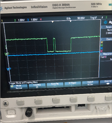
    Today we probed the RTS and Tx line of UART6 in J7. After sending "stty -F /dev/ttyS8 230400 crtscts" command, RTS looks good however when I try to send any data (e.g. echo -ne 'hello' > /dev/ttyS8)  on UART6 we don't see any activity on Tx line of UART6.

    See the picture below, the "Green" line is RTS line and "Blue" is Tx line of UART6 in J7. We were expecting if RTS is good we should see some data on Tx line. 

    Thanks,

    Satish

  • Hi Satish,

    Just double check if all the pins are right:

    J721E_IOPAD(0x210, PIN_INPUT, 1) /* (W3) MCAN1_RX.UART6_CTSn */
    J721E_IOPAD(0x214, PIN_OUTPUT, 1) /* (V4) MCAN1_TX.UART6_RTSn */
    J721E_IOPAD(0x218, PIN_INPUT, 8) /* (W2) I3C0_SCL.UART6_RXD */
    J721E_IOPAD(0x21c, PIN_OUTPUT, 8) /* (W1) I3C0_SDA.UART6_TXD */


    W3 --> CTS
    V4 --> RTS
    W2 --> RXD
    W1 --> TXD

    Hope your schematics are reflecting the same combination?

    Another combination i see is:

    T24--> TXD
    T27--> RXD
    AC27-->RXD
    Ab26 -->TXD

    T23 --> RTS
    R23 --> CTS

    U24 --> TXD
    U27 --> Rxd

    That is one thing to double check.

    If that is all good then:
    Let pc send data to our SOC and see how scope behaves (All 4 lines CTS/RTS/Rx/Tx).

    Regards,
    Keerthy

  • Hi Keerthy,

    The first DT is the correct one in my case.

    Regarding PC to SoC data send. - I don't have UART6 exposed to connect to PC. UART6 is available inside J7 but there is no direct connection exposed to connect it to PC.

    Do you think we can test this code on J7-evm board?

  • Hi Satish,

    UART6 pins are coming out on multiple balls.

    You can look at the sysconfig tool:


    It should be possible to mux.


    Best Regards,
    Keerthy

  • Hi Keerthy,

    What is sysconfig tool? Is it TI pinmux tool?

    Thanks,

    Satish

  • Thanks John. That is correct.

    - Keerthy