

Hi All,
I would like to ask some questions on power plane coverage.
I have found that there are several regions on EVM6437 belonging to input/output connectors are selectively covered/uncovered by power plane copper.
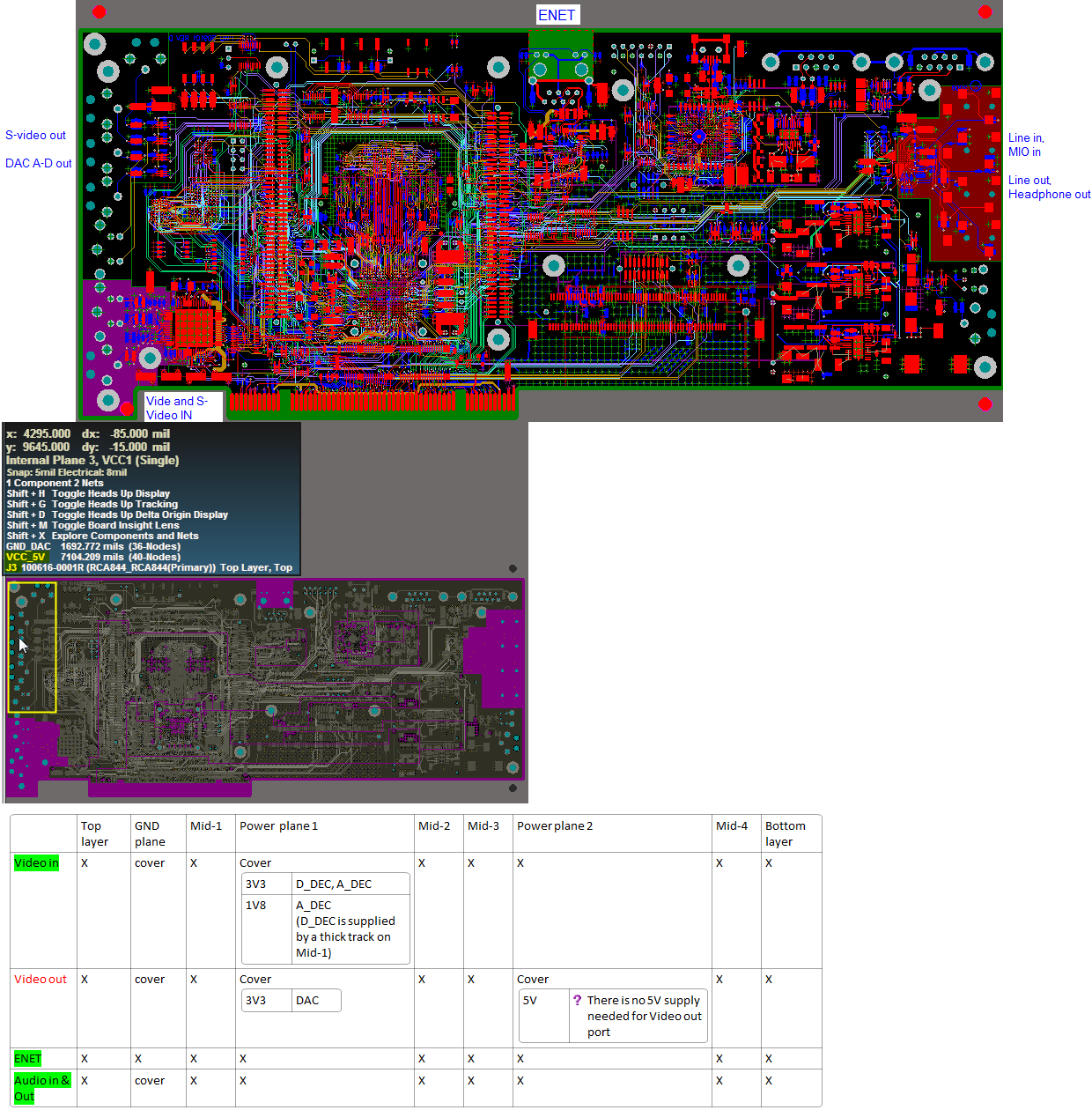
In the first part of the attached image, the positions of connectors
1. Video in
2. Video out
3. ENET
4. Audio in & out
are marked. We see that for [2. Video out] region there are no polygon region on that. Because polygon region translate negatively into no-copper area on internal planes, the fact there are no polygon region means this area is covered by all internal planes. However, for all [1, 3, 4] connectors’ area there are polygon regions over them, which means copper on some of the internal planes over them will be removed.
Their summary is listed in the table at the bottom. The left column is connector area, and the upper row is planes. Letter ‘X’ means the corresponding plane has no copper over the area, while “cover” means the corresponding plane covers the area.
I have compared with the schematics and confirmed that for all [1, 2, 4] connectors, only on necessary planes there are copper over the area. They are listed in smaller tables within cells. For example, [1. Video in] needs {GND, 3V3D_DEC, 3V3A_DEC and 1V8A_DEC} supply, which are all provided by power plane 1, so power planes 1 covers this area. There is not any need for supply from power plane 2, so power plane 2 has no copper over there.
My guess is: the reason for not extending unused power plane copper to areas is probably for reducing possible noise or interference? Is it true? What is the physics here?
But there is one inconsistency that I have found. For [2. Video out] area, although from schematics one can found there is no need there for 5V supply at all, yet there is still full 5V power plane copper coverage over that. Why is this? If this is the correct design then my previous guess could be wrong. Which is correct? How should I handle this area?
Thanks,
Zheng