

Hi All,
I would like to ask a question on via placement.
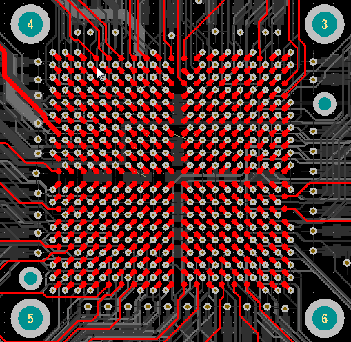
In the PCB design of EVM6437, vias of DM6437’s BGA pins are arranged in a rectangular grid with mostly likely equal horizontal and vertical distance.
My question is that can deviations be allowed? I do not know if the vias of EVM6437 are generated using some automated tools or command, by for my own design I have to place many of the vias manually, which of course is subject to some degree of inaccuracy from the ideal grid points; in addition, routing tracks out of the grid can sometimes also cause displacement of vias. Although I tried my best to adjust the positions to make them as close to an ideal grid as possible, that is still not perfect.
I think as long as there are sufficient distances between vias so there is not contact, then the signal can go through vias to other planes, and in principle there should be no problem. But does PCB manufacturer has requirement on equal horizontal and vertical distance? Basically, does there drilling require equal horizontal and vertical distance?
And does this have any effect on soldering? Would a uniform grid make soldering better? Could slight deviation cause connection error?
Thanks,
Zheng
