This thread has been locked.

If you have a related question, please click the "Ask a related question" button in the top right corner. The newly created question will be automatically linked to this question.

Question on EVM66437 Gerber file

Anonymous
Anonymous

Hi All,


I would like to ask a question on Gerber files.


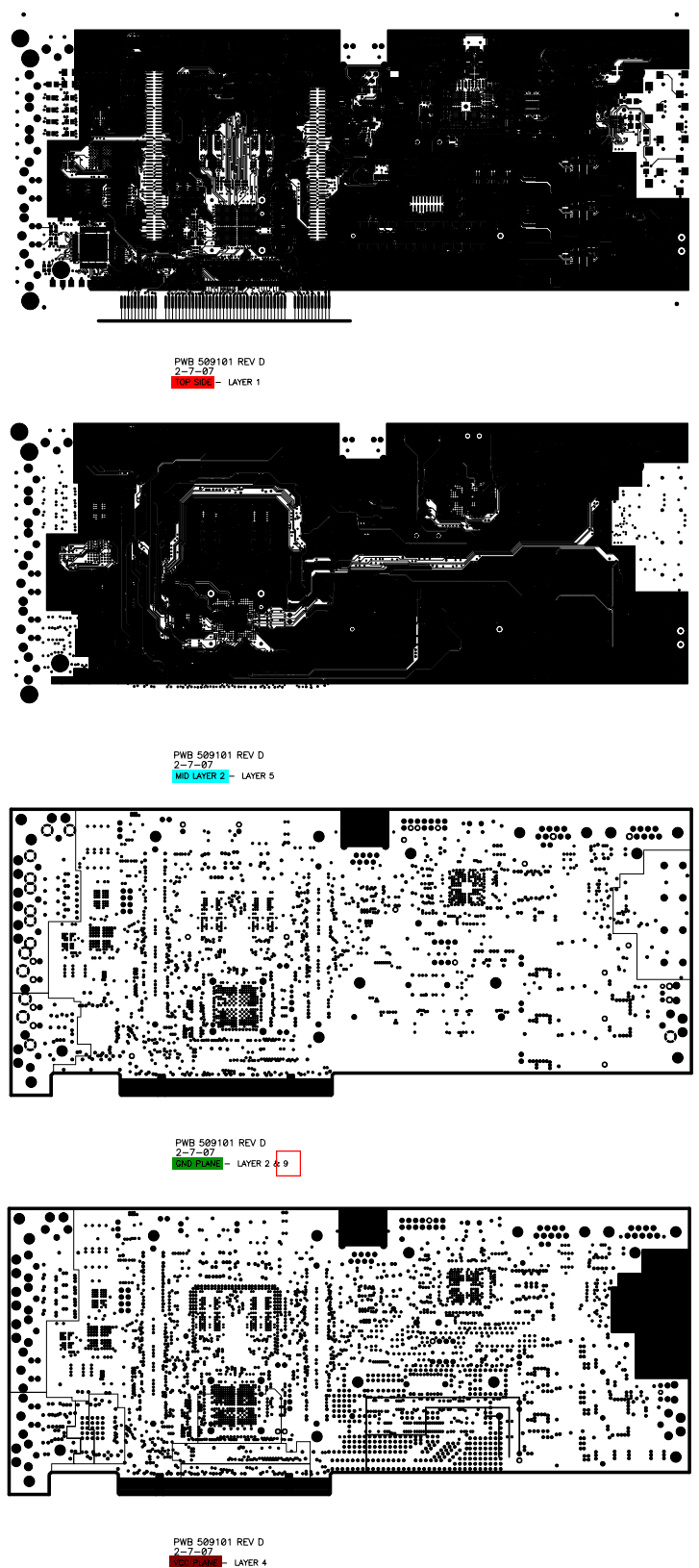
For the PDF Gerber file of EVM6437, I found that there seems to be some difference between signals and internal planes (power and ground).


For the upper two subimages which are all signals {top, Mid-layer 2}, the areas covered by copper are in black.


For the bottom two images which are power planes {GND, power}, the areas covered by copper are in white.


So why the representations are different?


Thanks,

Zheng

  • This is a convention of most layout CAD tools.  The power planes (VDD, GND, etc) are implemented as an "inverse" layer.  Meaning, where you see color (black in this case) is where there is NOT copper.  For the signal planes, where you see color, there IS copper.

    Again, this is generally a convention of the CAD tools and not specific to the EVM from TI.

  • Anonymous
    0 Anonymous in reply to BrandonAzbell

    Dear Brandon,

    I see it, thanks very much.

    Zheng