This thread has been locked.

If you have a related question, please click the "Ask a related question" button in the top right corner. The newly created question will be automatically linked to this question.

TDA4VM: PDK PCIe LLD How to access/configure physical functions and basic questions

Part Number: TDA4VM
Other Parts Discussed in Thread: SYSBIOS, AM6421

Hi Ti,

I would like to use PCIe to communicate between multiple TDA4-SoCs. Basically, I try to implement the proposal which was posted here:

https://e2e.ti.com/support/processors/f/processors-forum/953095/tda4vm-forward-access-from-one-pcie-port-subsystem-to-another-pcie-port-without-involving-a-cpu?tisearch=e2e-sitesearch&keymatch=pcie%2520chain#

I've experimented with PCIe and Linux and came to conclusion that due to linux scheduler mechanizm (TI does not support Linux RT Kernel for TDA4, "only" preemptive patched) the jitter of PCIe transaction is for our cases to high. Especially if the device receives network data, which has high/er/est priority compared to kernel work queues.

Therefore I try to implement a "kind of Non-Transparent-Bridge"-Solution with TI PCI LLD, which uses SysBios and runs on dedicated R5F to hopefully improve determinism and decrease jitter times.

There exists a PCIe example for AM65, I used that code and got the example running on two TDA4VMEVM. Data transfer between RC and EP without UDMA works.

I try to dig into PCIe Gen3 Specification, the functionality of TDA4 PCIe-modules but there are some questions left, which I hope you can provide me some support.
I think the the recent version of TRM Chapter PCIe Subsystem is incomplete and the PCIe LLD is still under development.

Q1: At some LLD code, I stumbled over comments which refer to "rev1 hw rev2 hw". Example: /drv/pcie/pcie.h Line 10504

  /**
   * @brief [rw] Region Index
   *
   * On rev 1 hw, this corresponds to REGION_INDEX
   * On rev 2 hw, this is virtual sw register to demux 16 inbound/outbound regions
   *
   * Outbound region, from 0 to 15.
   * Inbound region, from 0 to 3 (rev 1) or 0 to 15 (rev 2)
   *
   * Field size: 4 bits
   */
  uint8_t regionIndex;
} pciePlconfIatuIndexReg_t;
/* @} */

Which "hw rev" is implemented in TDA4 and AM6421?

Q2: How do I access/configure physical functions with the LLD? I need multiple physical functions on the same PCIe module. After my first glance in the LLD code I get impression that this is not supported. At some configuration functions there is always refered hardcoded to physical function 0. Example: /drv/pcie/src/v3/pciev3_plconf.c Line 365

/*****************************************************************************
 * Combine and write the PL CONF iATU Region Lower Base Address register
 ****************************************************************************/
pcieRet_e pciev3_write_plconfIatuRegLowerBase_reg
(
  CSL_pcie_ep_coreRegs *baseAddr,
  const pciePlconfIatuIndexReg_t *simIatuWindow,
  pciePlconfIatuRegLowerBaseReg_t *swReg
)
{
  uint32_t new_val = swReg->raw;
  pcieRet_e retVal = pcie_RET_OK;
  /* Don't need to check NULL this is internal API */
  uint8_t regionIndex = simIatuWindow->regionIndex;

  pcie_range_check_begin;

  if (regionIndex < 16)
  {
    if (simIatuWindow->regionDirection == 0U)
    {
       /* 0U == OUTBOUND */
       pcie_setbits(new_val, CSL_PCIE_EP_CORE_ATU_WRAPPER_OB_0_ADDR0_DATA, swReg->iatuRegLowerBase);
       pcie_setbits(new_val, CSL_PCIE_EP_CORE_ATU_WRAPPER_OB_0_ADDR0_NUM_BITS, swReg->zero);

       swReg->raw = baseAddr->ATU_WRAPPER_OB[regionIndex].ADDR0 = new_val;
    }
    else
    {
       /* INBOUND */
       pcie_setbits(new_val, CSL_PCIE_EP_CORE_ATU_FUNC0_WRAPPER_IB_EP_0_ADDR0_DATA, swReg->iatuRegLowerBase);

       swReg->raw = baseAddr->ATU_FUNC_WRAPPER_IB_EP[0][regionIndex].ADDR0 = new_val<<8;

       retVal = pcie_range_check_return;
    }
  }
  else
  {
    retVal = pcie_RET_RANGECHK;
  }

  return retVal;
} /* pciev3_write_plconfIatuRegLowerBase_reg */

During configuring iATU: ATU_FUNC_WRAPPER_IB_EP[0] <- Hardcoded index 0 ? Maybe I am wrong here.

Q3: Following Screenshot is from TRM:
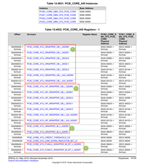
For me, it is not clear whats the difference between group 1 and group2, and between group 3 and 4.
There are 16 instances of group 1 and 2. Are they refering to virtual functions? If yes, how do I assign them to a specific virtual function?

There are 3 instances of group 3. Whats the purposes of these?

And finally there are 16 * 8 instances of group 4. I guess these belongs to specific virtual function + BAR idx?

Thank you very much for support in advance.. I think there might come up more questions Slight smile

Best regards,
Thomas

  • Thomas:

    Please answers to your questions:

    Q1: PCIe in TDA4 is defined as "PCIE_REV3_HW". The AM64 used the same hardware, but I don't think the example code is buildable for AM64. You can see the detailed definition of the macro in:

       PDK\packages\ti\drv\pcie\example\sample\src\pcie_sample.c

    Q2: you are right. The example code only support one PF. 

    Q3: Difference between Group 1 and 2 as you marked - there are two master ports from each PCIe controller connected to the CBASS, one called High Priority (HP), and another called Low Priority (LP) port. As shown in Figure 12-1261. You may take a look at an appNote under AM65:

        https://www.ti.com/lit/pdf/spraci6

    to understand a bit more about the HP/LP ports for PCIe integration. TDA4 used the similar architecture. 

    Group 3: the "k=0,1,2" refers to the BAR0, 1, and 7, as explained in Section Root Port Inbound PCIe to AXI Address Translation.

    Group 4: these are for EP inbound address translation, where there are 7 (register index seem to be 8) BARs supported per function. This is explained in 12.2.3.4.3.1.2 End Point Inbound PCIe to AXI Address Translation. 

    Please feel free to reopen the ticket if you run into additional questions or need further clarifications. 

    regards

    Jian

  • Hi Jian,

    thank you for your answers, they are really helpful.

    Nevertheless I have one more question: I try to understand how to use/extend the TI PCIe LLD code to configure multiple PCIe physical functions on the same PCIe module.

    Basically, TI provides for the TDA4 4 different functions to configure/setup PCIe module which depends on the preconfigured physical function number:

    • pcieRet_e Pciev3_atuRegionConfig
    • pcieRet_e Pciev3_cfgBar
    • pcieRet_e Pciev3_writeRegs
    • pcieRet_e Pciev3_readRegs

    All these functions take a Pcie_Handle as argument, which holds/points to a Pciev3_DevParams structure. The Pciev3_DevParams structure itself holds an index of the used physical function number (which comes into play when accessing pf-depended registers).

    The instances of this structure are defined in /drv/pcie/soc/j721e/src/pcie_soc.c

    Example:


    Pciev3_DevParams pcieDevParamsDev1 =
    {
    (volatile uint32_t *)(CSL_CTRL_MMR0_CFG0_BASE + CSL_MAIN_CTRL_MMR_CFG0_PCIE0_CTRL),
    (volatile uint32_t *)(CSL_CTRL_MMR0_CFG0_BASE + CSL_MAIN_CTRL_MMR_CFG0_PCIE_REFCLK0_CLKSEL),
    (void *)CSL_PCIE0_CORE_USER_CFG_USER_CFG_BASE,
    (void *)CSL_PCIE0_CORE_PCIE_INTD_CFG_INTD_CFG_BASE,
    1, /* one lane */
    3, /* default to GEN3 */
    0 /* use PF 0 */
    };

    So, instance pcieDevParamsDev1 is setup to use PF 0.

    Is it intended to create 5 additional Pciev3_DevParams instances, which are equal except of the PF number, to configure/enable all 6 physical functions of the same PCIe module?

    I'm not so sure about this, since other structures which holds these Pciev3_DevParams instances are limited to pcie_MAX_PERIPHS which is defined to "4".

    Example:  (drv/pcie/pcie.h)

    /**
    * @ingroup pcielld_api_structures
    * @brief Specification of Pcie_DeviceCfg
    *
    * The Pcie_DeviceCfg is used to specify device level configuration
    * to the LLD.
    */
    #define pcie_MAX_PERIPHS 4 /**< Maximum peripherals (base addresses) supported by LLD */
    typedef struct
    {
    Pcie_DeviceCfgBaseAddr *basesPtr[pcie_MAX_PERIPHS]; /**< base addreses */
    Pcie_FxnTable *fxnTablePtr[pcie_MAX_PERIPHS]; /**< function pointers */
    } Pcie_DeviceCfg;

    Best regards,
    Thomas

  • Thomas, 

    I never looked this portion of the code so pls take a grain of salt of my answers - the pcie_MAX_PERIPHS refers to maximum number of controllers (there are 4 PCie controllers on TDA4) instead of PFs on the same controller. Then the code use the index to point to the correct base address of the controller. PFs will need to be setup within the controller, which the example code never implemented. 

    regards

    jian 

  • Hi Jian,

    yes, you are right. I think also pcie_MAX_PERIPHS correlates to the maximum number of pcie modules/controllers within the SoC.

    But the structure of Pciev3_DevParams just let me configure/use only one single physical function.

    I could not imagine that the author of this driver lib limited the whole functionality to just one physical function per module. So I hoped I miss something here. For example just define multiple Pciev3_DevParams with the same base address but different physical function numbers. But this would also not work, since of the limitation of some arrays to the pcie_MAX_PERIPHS.

    Is it possible to ask the author of this driver lib about this topic?

    Best regards,
    Thomas

  • Thomas, 

    The original author of this code is no longer with TI so I won't be able to reach him. But I looked src/pcieinit.c where each handle was initialized, it seems assumed ONLY one function per handle, up to pcie_MAX_PERIPHS. 

    The example code was extended from a previous device that only support 1 PF, though user can extend handles across PFs. 

    I added the MF support for the example code to our work backlog, but I doubt it will meet your schedule. 

    regards

    Jian

  • Thank you very much jian, you confirmed my guesses. So, I'll modify and implement "multi pf" to the TI LLD driver.

    I will reopen this ticket if more questions arises.

    Best regards,
    Thomas