


Part Number: AM5729
Other Parts Discussed in Thread: AM5728
Dear Champs,
My customer is using AM5729 IDK board and connect their custom LCD board to AM5729 IDK board.
With their custom LCD board, they found LCD brightness was not controlled as below.
ehrpwm1 is used to control backlight. SW SDK is v6.3.
~~~~~~~
root@am57xx-evm:~# cat /sys/kernel/debug/pwm
platform/48442200.pwm, 2 PWM devices
pwm-0 ((null) ): period: 0 ns duty: 0 ns polarity: normal
pwm-1 ((null) ): period: 0 ns duty: 0 ns polarity: normal
platform/48440200.pwm, 2 PWM devices
pwm-0 (LCD ): requested period: 50000 ns duty: 0 ns polarity: normal
pwm-1 ((null) ): period: 0 ns duty: 0 ns polarity: normal
platform/4843e200.pwm, 2 PWM devices
pwm-0 ((null) ): period: 0 ns duty: 0 ns polarity: normal
pwm-1 ((null) ): period: 0 ns duty: 0 ns polarity: normal
:
:
root@am57xx-evm:/# echo 10 > /sys/class/backlight/backlight/brightness
-sh: echo: write error: Invalid argument
~~~~~~~~
But, when they control it manually in sysfs as below, it works.
echo 0 > /sys/class/pwm/pwmchip2/export
echo 50000 > /sys/class/pwm/pwmchip2/pwm0/period
echo 1 > /sys/class/pwm/pwmchip2/pwm0/enable
echo 0 > /sys/class/pwm/pwmchip2/pwm0/duty_cycle
echo 47647 > /sys/class/pwm/pwmchip2/pwm0/duty_cycle
root@am57xx-evm:~# cat /sys/kernel/debug/pwm
platform/48442200.pwm, 2 PWM devices
pwm-0 (LCD ): requested period: 50000 ns duty: 0 ns polarity: normal
pwm-1 ((null) ): period: 0 ns duty: 0 ns polarity: normal
platform/48440200.pwm, 2 PWM devices
pwm-0 (sysfs ): requested enabled period: 50000 ns duty: 47647 ns polarity: normal
pwm-1 ((null) ): period: 0 ns duty: 0 ns polarity: normal
platform/4843e200.pwm, 2 PWM devices
pwm-0 ((null) ): period: 0 ns duty: 0 ns polarity: normal
pwm-1 ((null) ): period: 0 ns duty: 0 ns polarity: normal
~~~~~~~~~~~~~~
Could you please let me know your idea what is the issue in this case?
They are afraid there is an issue in their modification in device tree or kernel driver setting.
They have an experience to develop AM335x, but it is much different with AM5728.
For HW change,
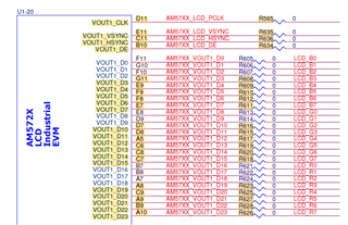
in their custom LCD board, they are using RGB565 mode and connected as below.
D11 : LCD_CLK, E11 : LCD_VSYNC, C11 : LCD_HSYNC, B10 : LCD_DE,
G11, E9, F9, F8, E7, D7, D8, A5, C6, C8, C7, A8, C9, A9, B9, A10 : LCD_DATA(RGB565)
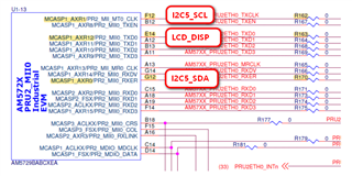
E14 : GPIO, connected to DISP of LCD to control LCD.
AG3 : GPIO, connected to Touch Interrupt
E6 : ehrpwm2A, PWM LCD Backlight
There is touch IC connected through I2C, and I2C5 was used for it.
And their device tree for LCD and PWM is as below.
/ {
aliases {
display = &lcd;
};
lcd:display {
// pinctrl-names = "default";
// pinctrl-0 = <&lcd_pins_default>;
status = "okay";
//compatible = "osddisplays,osd070t1718-19ts", "panel-dpi";
compatible = "panel-dpi";
//compatible = "ti,tilcdc,panel";
label = "lcd";
backlight = <&lcd_bl>;
enable-gpios = <&gpio3 11 GPIO_ACTIVE_HIGH>; // AH4.vin1a_d7.gpio3_11
panel-timing {
clock-frequency = <18000000>; // 18 Mhz (Min. 4 Mhz) for N3/NTMini/NTA
hactive = <480>;
vactive = <272>;
hfront-porch = <2>;
hback-porch = <45>;
vfront-porch = <4>;
vback-porch = <12>;
hsync-len = <41>;
vsync-len = <10>;
hsync-active = <0>;
vsync-active = <0>;
bpp = <16>;
de-active = <1>;
pixelclk-active = <1>;
};
port {
lcd_in: endpoint {
remote-endpoint = <&dpi_out>;
//data-lines = <24>;
data-lines = <16>;
};
};
};
lcd_bl:backlight {
status = "okay";
compatible = "pwm-backlight";
// The hardware numbers these subsystems 1,2,3 but the dra7.dtsi file names them 0,1,2.
// https://e2e.ti.com/support/processors/f/processors-forum/665012/linux-am5728-lcd-backlight-issue
// TRM Pg.407
// PWMSS1 TP_PWMSS1_TARG 0x4843_E000
// PWMSS2 TP_PWMSS2_TARG 0x4844_0000
// PWMSS3 TP_PWMSS3_TARG 0x4844_2000
pwms = <&ehrpwm1 0 50000 0>; // E6.vin2a_d9.ehrpwm2A
pwm-names = "LCD";
/* Anything lower than 241 is no longer visible */
brightness-levels = <0 243 245 247 249 251 252 253 255>;
default-brightness-level = <8>;
};
&dss {
status = "ok";
vdda_video-supply = <&vdd_1v8_pll>;
ports {
#address-cells = <1>;
#size-cells = <0>;
port@0 {
reg = <0>;
dpi_out: endpoint {
remote-endpoint = <&lcd_in>;
//data-lines = <24>;
data-lines = <16>;
};
};
};
};
&ehrpwm0 {
status = "okay";
};
&epwmss0 {
status = "okay";
};
&ehrpwm1 {
status = "okay";
};
&epwmss1 {
status = "okay";
};
&ehrpwm2 {
status = "okay";
};
&epwmss2 {
status = "okay";
};
And the below is the booting message.
root@am57xx-evm:/dev# dmesg | grep dss
[ 0.648687] omapdss_dss 58000000.dss: Linked as a consumer to regulator.20
[ 0.648772] DSS: dss_runtime_get
[ 0.648814] DSS: dss_restore_context
[ 0.648835] DSS: dss_runtime_put
[ 0.649033] omapdss_dispc 58001000.dispc: OMAP DISPC rev 5.1
[ 0.649166] omapdss_dss 58000000.dss: bound 58001000.dispc (ops dispc_component_ops)
[ 0.649227] DSS: dss_save_context
[ 0.650203] DSS: dss_restore_context
[ 0.650399] DSS: dss_save_context
[ 0.650444] DSS: dss_runtime_get
[ 0.650477] DSS: dss_restore_context
[ 0.674406] DSS: dss_runtime_put
[ 0.674419] DSS: dss_save_context
[ 0.674484] DSS: dss_restore_context
[ 0.674623] DSS: dss_save_context
[ 0.674688] DSS: dss_restore_context
[ 0.674825] DSS: dss_save_context
[ 0.674890] DSS: dss_restore_context
[ 0.675025] DSS: dss_save_context
[ 0.675091] DSS: dss_restore_context
[ 0.675226] DSS: dss_save_context
[ 0.675906] APPLY: omap_dss_mgr_apply(lcd)
[ 0.675920] APPLY: omap_dss_mgr_apply(lcd)
[ 0.675929] APPLY: omap_dss_mgr_apply(tv)
[ 0.675937] APPLY: omap_dss_mgr_apply(lcd2)
[ 0.675945] APPLY: omap_dss_mgr_apply(lcd3)
[ 0.675996] DSS: dss_restore_context
[ 0.676026] DSS: dss_runtime_get
root@am57xx-evm:/dev# dmesg | grep drm
root@am57xx-evm:/dev# dmesg | grep lcd
[ 0.675906] APPLY: omap_dss_mgr_apply(lcd)
[ 0.675920] APPLY: omap_dss_mgr_apply(lcd)
[ 0.675937] APPLY: omap_dss_mgr_apply(lcd2)
[ 0.675945] APPLY: omap_dss_mgr_apply(lcd3)
[ 0.707778] omapfb omapfb: using display 'lcd' mode 480x272
root@am57xx-evm:/dev# dmesg | grep backlight
[ 0.646890] pwm-backlight backlight: GPIO lookup for consumer enable
[ 0.646902] pwm-backlight backlight: using device tree for GPIO lookup
[ 0.646924] of_get_named_gpiod_flags: can't parse 'enable-gpios' property of node '/backlight[0]'
[ 0.646942] of_get_named_gpiod_flags: can't parse 'enable-gpio' property of node '/backlight[0]'
[ 0.646954] pwm-backlight backlight: using lookup tables for GPIO lookup
[ 0.646965] pwm-backlight backlight: No GPIO consumer enable found
[ 0.647001] pwm-backlight backlight: backlight supply power not found, using dummy regulator
[ 0.647068] pwm-backlight backlight: Linked as a consumer to regulator.0
Thanks and Best Regards,
SI.
