


Other Parts Discussed in Thread: OMAP-L138, TLV320AIC3106, OMAP-L137
Hello,
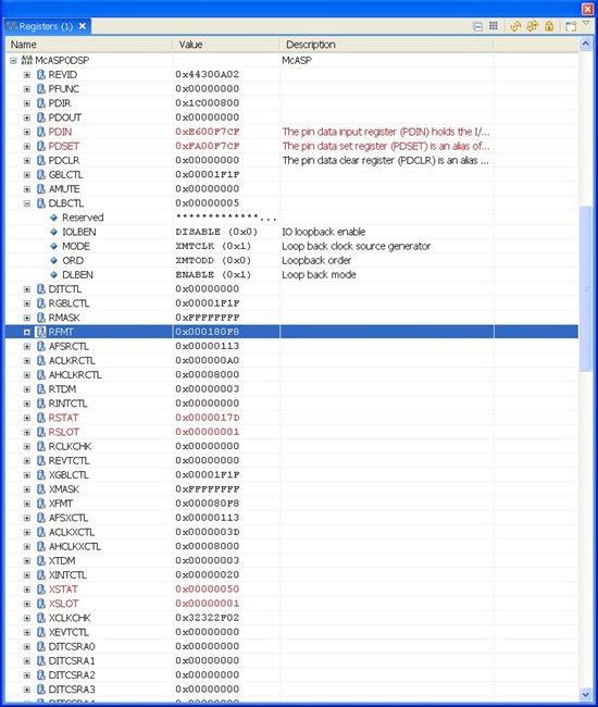
I would appreciate any simple McASP loopback example code for the C6748.
Regards,
Robert
Other Parts Discussed in Thread: OMAP-L138, TLV320AIC3106, OMAP-L137
Hello,
I would appreciate any simple McASP loopback example code for the C6748.
Regards,
Robert


 .
.