Part Number: AM62X-PET-CALC
Hi TI
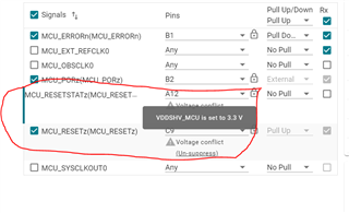
When i finish the PINMUX config and power domain config, there is confict message show as below,Can i suppress these two warning ?
As the MCU GPIO is 3v3 level ,so i connect the VDDSHV_MCU to 3v3 domain.
BR Jingcheng
Part Number: AM6442
Problem Description
The MCU+ SDK comes with a GPIO_INPUT_INTERRUPT example for R5FSS0-0. This example configures a GPIO pin to generate an interrupt and then registers an interrupt handler to service the GPIO interrupt. This example works out-of-the box with MCU+ SDK. However, when running Linux on A53 and NORTOS/FreeRTOS on other cores, this GPIO_INPUT_INTERRUPT does not work. It fails by reporting the following error:
[Error] Sciclient event config failed!!!
In this FAQ, we will cover the WHAT, WHY and HOW of the issue. We will discuss WHAT is causing the issue, WHY the issue happens and HOW to resolve the issue.
Part Number: SK-AM62
What is GPIO?
The General-Purpose Input/output (GPIO) peripheral provides dedicated general-purpose pins that can be configured as either inputs or outputs.
GPIO can be used in three modes:
*Input
*Output
*Interrupt
GPIO’s availability in the AM62X SDK:
The device has one or more instances of GPIO modules. The GPIO pins are grouped into banks (16 pins
per bank and 9 banks per module), which means that each GPIO module provides up to 144 dedicated
general-purpose pins with input and output capabilities; thus, the general-purpose interface supports up to 432 (3 instances × (9 banks × 16 pins)) pins. Since MCU_GPIO0_[23:143], GPIO0_[87:143], and GPIO1_[88:143] are reserved in this device, general purpose interface supports up to 198 pins.
GPIO Interrupt Connectivity in AM62X SDK:
The SOC on the AM62 uses an interrupt router to route pin interrupts to the corresponding core for all GPIO pins. If you configure an interrupt for each pin, your design will be complicated. Therefore, the routing concept is designed to minimize the overhead of all GPIO interrupts in the SOC. So, user can control bank interrupts and individual pin interrupts.

Part Number: TMS320C6678
How to set Static and DHCP IP configuration using PDK in C667x and C665x family Processors ?
Part Number: PROCESSOR-SDK-TDAX
VHWA has totally 6 drivers in the PDK and each driver requires many DMA channels to do transfers. In addition to one main ring, each channel requires two additional rings, one for output completion and other for tear down completion. This increases the total ring requirement for the VHWA driver.
This article explains how to reduce ring usage in VHWA driver.
I am not using one of the cores on my TI processor. How do I disable that core, so that I can free up more memory, peripherals, etc for my other cores?
.
This FAQ will use AM64x as an example, but the same concepts apply for AM62x.
.
NOTE: This FAQ discusses how to disable non-Linux cores on the processor, like R5F (AM64x) and M4F(both AM64x & AM62x). For information on how to disable A53 cores and GPU cores that do not exist on a specific part number, please reference the FAQ rti_wdt_probe error on Linux boot.
For information on other multicore subjects, reference the FAQ Sitara multicore development and documentation.
UPDATE January 2024: The information in this FAQ has been added to the processor academy modules. This FAQ will not be maintained going forward.
Please find the latest information in the processor's academy > Multicore module > Multicore Development > Booting and disabling processor cores > Disabling remote cores:
AM62x
AM62Ax
AM64x
Part Number: AM3354
Hi there,
I am using the AM3354 CPU.
For cybersecurity, I want the JTAG port to be protected, to avoid others read out our binary code. The CPU can only be full ereased after this protection.
Please tell me how to achieve this. If it is not supported by AM3354, is there any similar way to have this protection?
An application note to show the detailed steps / configuration method will be more helpful.
BR,
Wenhai.
Part Number: TDA4VM
When testing SDL (Software Diagnostics Library) package on the TDA4VM, seeing LBIST HW POST Timeout logs as below.
BIST Example Application
Starting LBIST test on HWPOST - DMSC, index 0...
HW POST MCU Status : SDL_LBIST_POST_TIMEOUT
HW POST DMSC Status : SDL_LBIST_POST_TIMEOUT
Starting LBIST test on HWPOST - MCU, index 1...
HW POST MCU Status : SDL_LBIST_POST_TIMEOUT
HW POST DMSC Status : SDL_LBIST_POST_TIMEOUT
Part Number: AM6442
UPDATE: This FAQ has been replaced by the Multicore academy module, section "Application Development on Remote cores". Please refer to the associated processor academy. This FAQ will not be updated in the future.
The MCU+ "Hello World" example can be loaded by CCS. However, the project will fail to be loaded if the remote core is initialized by Linux. Why is that?
The Linux RemoteProc driver checks the remote core firmware for a resource table before it loads the firmware into a remote core. If the firmware does not have a resource table, then Linux will not load the firmware. That means that if we want to use Linux to load the "Hello World" example (or any example), then we need to make sure the project has a resource table in it.
How to add a resource table to an MCU+ project?
.
Note1: "remote core" means any core in the processor that is not the Linux cores. So from a Linux perspective, M4F and R5F are both "remote cores".
Note2: The same information applies to both M4F and R5F. For now, this FAQ will use M4F to demonstrate how to add a resource table.
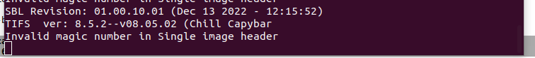
Part Number: TDA4VM
I'm trying to boot using SBL from OSPI on TDA4 device but I see the below error. What could be the issue?