This thread has been locked.

If you have a related question, please click the "Ask a related question" button in the top right corner. The newly created question will be automatically linked to this question.

[FAQ] AM625 / AM623 / AM62A / AM62P Design Recommendations / Commonly Observed Errors during Custom board hardware design – eMMC MEMORY Interface

Other Parts Discussed in Thread: AM62P

Hi TI Experts,

Is there a list of design recommendations or commonly observed errors  for eMMC MEMORY Interface during Custom board hardware design?

Below are some common queries i have 

1. Pullup recommendation 

2. Power supply and Sequencing 

3. Series resistor for eMMC clock output from the processor

4.Series resistors for Data and command signals 

5. Calibration resistor 

6. Alternate Part recommendations

7. Are these recommendations valid for AM64x

8. Is the  reset ANDing logic for the device required and any recommendations?

9. What is the default drive strength and can the drive strength be controlled?

  • Hi Board designers, 

    Refer below inputs:

    1. Pullup recommendation 

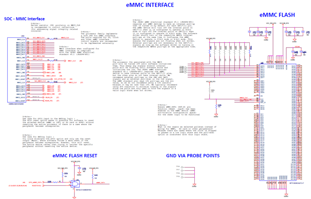
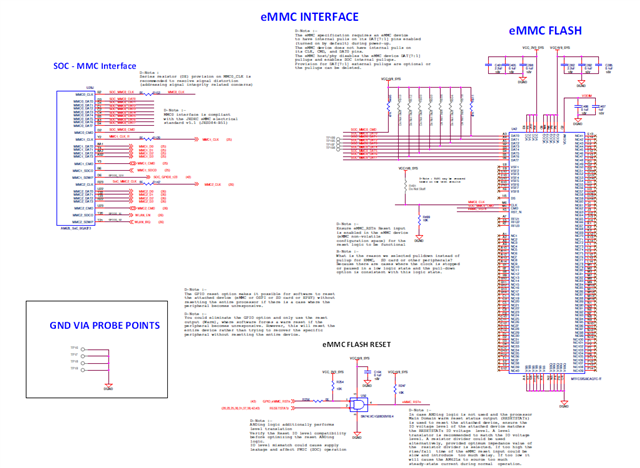
    The Pullup recommendations depend on the eMMC PHY implementation 

    AM62x and AM62Ax implement soft PHY

    In soft PHY implementation, the MMC0 pins have alternate functions that can be configured.

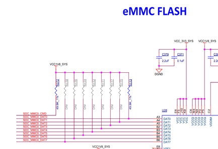
    Connect external pullup resistor for the data line (MMC0_DAT0) (close to eMMC device).
    eMMC device (as long as the eMMC device is compliant to the eMMC standard) has the pullups enabled for data signals
    D7..D1 by default. The eMMC device will turn off its D3..D1 pulls when entering 4-bit mode and D7..D1 pulls when entering 8-bit mode.
    The eMMC host software should turn on the respective DAT pulls when it changes the mode.

    AM62Px implements a hard PHY

    In hard PHY implementation, the MMCO pins have dedicate eMMC functionality. When not used, it is recommended to connect these pins as per the pin connectivity recommendations of the specific device data sheet.

    No external pull resistors are required for MMC0 since the PHY includes and dynamically controls the internal pull resistors as required for an eMMC.
    Pullups for D7..D0 and CMD are internally enabled during reset and after reset by the processor eMMC PHY.
    Pulldown is enabled for the DS pin and the clock output is driven low during reset and by the SS (The subsystem selected with MUXMODE determines the output buffer state) after reset.
    There are no PADCONFIG registers associated with the MMC0 pins.
    The internal pulls associated with the MMC0 pins are dynamically controlled by the MMC0 host and PHY.
    Provision for External pulls are not a requirement for the eMMC data, CMD, DS and the CLK signals.

    2. Power supply and Sequencing 

    The recommendation is to power the processor IO supply rail and the eMMC device from the same power source

    3. Series resistor for eMMC clock output from the processor

    it is  a good idea to place a series termination resistor as close as possible to the MMC0_CLK pin in case it is needed to dampen reflections caused by an impedance mismatch.

    4.Series resistors for Data and command signals 

    This is not a requirement. Optionally the series resistors can be included to  improve signal integrity and custom board design/layout dependent.

    5. Calibration resistor 

    Refer to the device specific data sheet for the recommendations including the resistor value.

    6. Alternate Part recommendations

    TI doesn't make specific component recommendations.
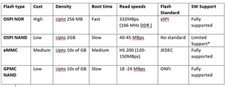
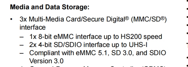
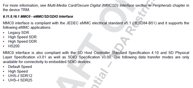
    From the hardware perspective the MMC0 port on the AM6 devices are  compatible with the eMMC standards. So there should not be any hardware issue operating with any eMMC compliant device. See the MMC0 timing section of the datasheet for the eMMC data transfer modes supported.

    7. Are these recommendations valid for AM64x

    AM64X implements hard PHY similar to AM62P. AM62P and the general queries 2..6 can be followed.

    8. Is the  reset ANDing logic for the device required and any recommendations?

    The ANDing logic provides flexibility to reset the attached memory device. Refer SK schematics for implementation.
    RESETSTATz output will satisfy the power-on and warm reset functions and can be used to reset the attached device. Ensure IO level compatibility between the RESETSTATz output and the attached device reset input. You will need a two input AND gate to insert the software controlled GPIO reset function for the case where software needs to initiate a reset to only
    A pullup and an isolation resistor is recommended for the SoC IO output connected to the ANDing logic near to the AND gate.
    When ANDing logic is not used, verify the IO compatibility of the SoC reset status output used and the attached memory device.

    9. What is the default drive strength and can the drive strength be controlled?

    These are typically about 40 ohms, but the customer should be using the IBIS model to determine the drive strength of the pins. 
    The drive strength must remain in the default state since this is the only condition used during timing closure of the peripherals.

    Regards,

    Sreenivasa