This thread has been locked.

If you have a related question, please click the "Ask a related question" button in the top right corner. The newly created question will be automatically linked to this question.

AM4378: eMMC boot

Part Number: AM4378

Dear,

I am working on AM4378 project and it is based on AM437x-gp-evm. I built sitara linux and boot from SD card now. It is working fine.

Now I wanted to transfer all linux files(MLO, uboot.img, kernel, file system, etc) to eMMC and boot it from eMMC.  How do i achieve this? 

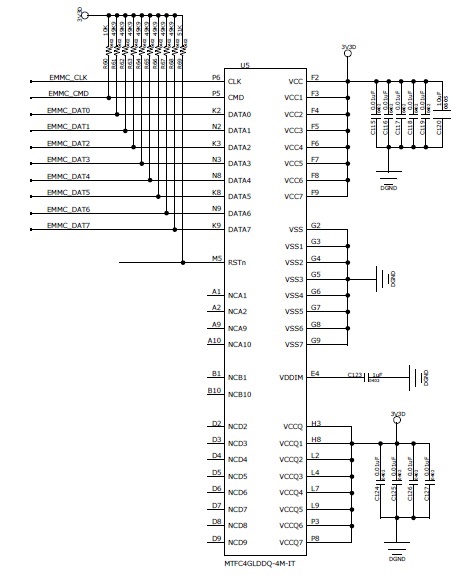
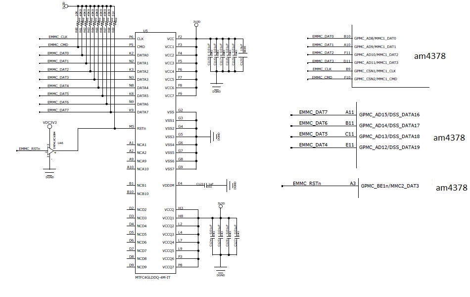
My  schematic is as follows

My boot sequence given below.

I am following the below link to update files and boot from eMMC,

http://processors.wiki.ti.com/index.php/Linux_Core_U-Boot_User's_Guide#Using_SD.2C_eMMC_or_USB_storage

I enter the following command from uboot,

U-Boot # printenv partitions
uuid_disk=${uuid_gpt_disk};name=rootfs,start=2MiB,size=-,uuid=${uuid_gpt_rootfs}
U-Boot # setenv uuid_gpt_disk ...first uuid...
U-Boot # setenv uuid_gpt_rootfs ...second uuid...
U-Boot # gpt write mmc 1 ${partitions}

When i enter "U-Boot # gpt write mmc 1 ${partitions} " , I got below error,

"Card did not respond to voltage select!
do_gpt: mmc dev 1 NOT available "

What could be the reason? How do i solve this problem?

Regards,
Winiston.P

  • Hi,

    Please post the connections on the AM437x side, and which Linux version you use.
  • Dear Biser,

    Linux version is "4.1.6-g52c4aa7" .    TI -SDK is 2.00.00  .Please see below schematic and U46 is not mounted.  R69 = 10K ohm. Remaining values are as per schematic.

    Regards,

    Winiston.P

  • Pins seem correct. I have notified the software team to comment on the software part. They will respond here.
  • Hi,

    Can you try executing:
    mmc rescan
    mmc info
    from u-boot prompt?

    If you get the same errors with these commands, please add CONFIG_MMC_TRACE & DEBUG, to enable a more verbose u-boot log & share your serial console output.

    Best Regards,
    Yordan

  • Dear Yordan,

    I executed the commands you said. I did not get any error messages. Please see my serial console output

    U-Boot# mmc rescan
    17: mmc rescan
    U-Boot# mmc info
    23: mmc info
    Device: OMAP SD/MMC
    Manufacturer ID: 74
    OEM: 4a60
    Name: USDU1
    Tran Speed: 50000000
    Rd Block Len: 512
    SD version 3.0
    High Capacity: Yes
    Capacity: 15 GiB
    Bus Width: 4-bit
    Erase Group Size: 512 Bytes
    U-Boot#

    Regards,

    Winiston.P

  • Dear Yordan,

    I am waiting for your reply to solve this issue.

    Regards,

    Winiston.P

  • Dear Yordan,

    I executed the commands you said. I did not get any error messages. Please see my serial console output

    U-Boot# mmc rescan
    17: mmc rescan
    U-Boot# mmc info
    23: mmc info
    Device: OMAP SD/MMC
    Manufacturer ID: 74
    OEM: 4a60
    Name: USDU1 
    Tran Speed: 50000000
    Rd Block Len: 512
    SD version 3.0
    High Capacity: Yes
    Capacity: 15 GiB
    Bus Width: 4-bit
    Erase Group Size: 512 Bytes
    U-Boot#

    I am waiting for your reply for long time...  Please let me know if you need any console output from my side.

    Regards,

    Winiston.P

  • Hi,

    Apologies for the delayed response.

    I meant switch to the problematic MMC1 (eMMC) and try to rescan & run the info commands...

    However, see if your pinmux settings are correct. See if you actually enable the mmc device in your board.c file.

    Best Regards,
    Yordan
  • Dear Yordan,

    1. I can not switch to MMC1(emmc). If i enter " U-Boot # mmc dev 1", it gives below error,

    "mmc dev 1

    Card did not respond to voltage select! "

    Is it a conflict in voltage?

    Note:I am using 3.3v bank for emmc.

    If i enter "mmc rescan & mmc info ", It gives, MMC0(sd card) information only.

    2. My pinmux settings seems to be correct. Please find attached dts file for your reference.

    2313.am437x-gp-evm.txt
    /* This file was auto-generated by TI PinMux on ‎22‎-‎07‎-‎2016 at ‎15‎:‎43‎:‎54. */
    /* This file should only be used as a reference.  Some pins/peripherals, */
    /* depending on your use case, may need additional configuration. */
    
    /* Some or all the pins from the following groups are not used by device tree 
       myrtc1
       usb_otg
       usb_host
       myadc1
       ram
    */
    
    /dts-v1/;
    
    #include "am4372.dtsi"
    #include <dt-bindings/pinctrl/am43xx.h>
    #include <dt-bindings/pwm/pwm.h>
    #include <dt-bindings/gpio/gpio.h>
    
    / {
    	model = "TI AM437x GP EVM";
    	compatible = "ti,am437x-gp-evm","ti,am4372","ti,am43";
    
    	aliases {
    		display0 = &lcd0;
    		serial3 = &uart3;
    	};
    
    	evm_v3_3d: fixedregulator-v3_3d {
    		compatible = "regulator-fixed";
    		regulator-name = "evm_v3_3d";
    		regulator-min-microvolt = <3300000>;
    		regulator-max-microvolt = <3300000>;
    		enable-active-high;
    	};
    
    	vtt_fixed: fixedregulator-vtt {
    		compatible = "regulator-fixed";
    		regulator-name = "vtt_fixed";
    		regulator-min-microvolt = <1500000>;
    		regulator-max-microvolt = <1500000>;
    		regulator-always-on;
    		regulator-boot-on;
    		enable-active-high;
    		gpio = <&gpio2 1 GPIO_ACTIVE_HIGH>;
    	};
    
    	vmmcwl_fixed: fixedregulator-mmcwl {
    		compatible = "regulator-fixed";
    		regulator-name = "vmmcwl_fixed";
    		regulator-min-microvolt = <1800000>;
    		regulator-max-microvolt = <1800000>;
      		/*belowlines added by wini */
                     startup-delay-us = <70000>;
    		/* WLAN_EN GPIO for this board - Bank0, pin18 */
    		gpio = <&gpio0 18 GPIO_ACTIVE_HIGH>;
    		enable-active-high;
    		
    	};
    
    	lcd_bl: backlight {
    		compatible = "pwm-backlight";
    		pwms = <&ecap0 0 50000 PWM_POLARITY_INVERTED>;
    		brightness-levels = <0 51 53 56 62 75 101 152 255>;
    		default-brightness-level = <8>;
    	};
    	
    	lcd0: display {
    		compatible = "panel-dpi";
    		label = "lcd";
    
    		panel-timing {
    			clock-frequency = <25000000>;
    			hactive = <640>;
    			vactive = <480>;
    			hfront-porch = <12>;
    			hback-porch = <52>;
    			hsync-len = <96>;
    			vback-porch = <31>;
    			vfront-porch = <11>;
    			vsync-len = <2>;
    			hsync-active = <0>;
    			vsync-active = <0>;
    			de-active = <1>;
    			pixelclk-active = <1>;
    		};
    
    		port {
    			lcd_in: endpoint {
    				remote-endpoint = <&dpi_out>;
    			};
    		};
    	};
    
    /*below lines added by wini */
    
    	/* fixed 12MHz oscillator */
    	refclk: oscillator {
    		#clock-cells = <0>;
    		compatible = "fixed-clock";
    		clock-frequency = <12000000>;
    	};
    
    	/* fixed 32k external oscillator clock */
    	clk_32k_rtc: clk_32k_rtc {
    		#clock-cells = <0>;
    		compatible = "fixed-clock";
    		clock-frequency = <32768>;
    	};
    
    
    	sound0: sound@0 {
    		compatible = "simple-audio-card";
    		simple-audio-card,name = "AM437x-GP-EVM";
    		simple-audio-card,widgets =
    			"Headphone", "Headphone Jack",
    			"Microphone", "Microphone Jack",
    			"Speaker", "External Speaker";
    		simple-audio-card,routing =
    			"Headphone Jack",	"HPLOUT",
    			"Headphone Jack",	"HPROUT",
    			"MIC3L",		"Microphone Jack",
    			"MIC3R",		"Microphone Jack",
    			"External Speaker",	"MONO_LOUT";
    		simple-audio-card,format = "dsp_b";
    		simple-audio-card,bitclock-master = <&sound0_master>;
    		simple-audio-card,frame-master = <&sound0_master>;
    		simple-audio-card,bitclock-inversion;
    
    		simple-audio-card,cpu {
    			sound-dai = <&mcasp1>;
    			system-clock-frequency = <12000000>;
    		};
    
    		sound0_master: simple-audio-card,codec {
    			sound-dai = <&tlv320aic3106>;
    			system-clock-frequency = <12000000>;
    		};
    	};
    
    	audio_mstrclk: mclk_osc {
    		compatible = "fixed-clock";
    		#clock-cells = <0>;
    		clock-frequency = <12000000>;
    	};
    
    };
    
    &am43xx_pinmux {
    	pinctrl-names = "default", "sleep";
      /* modified by wini */
    	pinctrl-0 = <&wlan_irq_pins_default &ddr3_vtt_toggle_default &debugss_pins>;
       /* added by wini */
            pinctrl-1 = <&wlan_irq_pins_sleep>; 
    
    	ddr3_vtt_toggle_default: ddr_vtt_toggle_default {
    		pinctrl-single,pins = <
    			0x8C (DS0_PULL_UP_DOWN_EN | PIN_OUTPUT_PULLUP | DS0_FORCE_OFF_MODE | MUX_MODE7) /* (A12) gpmc_clk.gpio2[1] */
    		>;
    	};
    	
    	i2c0_pins: i2c0_pins {
    		pinctrl-single,pins = <
    			0x18c (PIN_INPUT_PULLUP | SLEWCTRL_FAST | MUX_MODE0)  /* (Y22) i2c0_scl.i2c0_scl */
    			0x188 (PIN_INPUT_PULLUP | SLEWCTRL_FAST | MUX_MODE0)  /* (AB24) i2c0_sda.i2c0_sda */
    			
    		>;
    	};
    	
    	i2c1_pins_default: i2c1_pins_default {
    		pinctrl-single,pins = <
    			0x240 (PIN_INPUT_PULLUP | SLEWCTRL_FAST | MUX_MODE1) /* (G20) gpio5_10.I2C1_SCL */
    			0x248 (PIN_INPUT_PULLUP | SLEWCTRL_FAST | MUX_MODE1) /* (E25) gpio5_12.I2C1_SDA */
    		>;
    	};
    	
    	sd_card_pins_default: sd_card_pins_default {
    		pinctrl-single,pins = <
    			0x100 (PIN_INPUT_PULLUP | MUX_MODE0 ) /* (D1) mmc0_clk.mmc0_clk */
    			0x104 (PIN_INPUT_PULLUP | MUX_MODE0 ) /* (D2) mmc0_cmd.mmc0_cmd */
    			0xfc (PIN_INPUT_PULLUP | MUX_MODE0 ) /* (C1) mmc0_dat0.mmc0_dat0 */
    			0xf8 (PIN_INPUT_PULLUP | MUX_MODE0 ) /* (C2) mmc0_dat1.mmc0_dat1 */
    			0xf4 (PIN_INPUT_PULLUP | MUX_MODE0 ) /* (B2) mmc0_dat2.mmc0_dat2 */
    			0xf0 (PIN_INPUT_PULLUP | MUX_MODE0 ) /* (B1) mmc0_dat3.mmc0_dat3 */
    			0x160 (PIN_INPUT_PULLUP | MUX_MODE5 ) /* (R25) spi0_cs1.mmc0_sdcd */
    		>;
    	};
    	
    	/* Optional sleep pin settings. Must manually enter values in 	the below skeleton. */
    	sd_card_pins_sleep: sd_card_pins_sleep {
    		pinctrl-single,pins = <
    			0x100 (PIN_INPUT_PULLDOWN | MUX_MODE7 ) /* (D1) mmc0_clk.mmc0_clk */
    			0x104 (PIN_INPUT | PULL_DISABLE | MUX_MODE7 ) /* (D2) mmc0_cmd.mmc0_cmd */
    			0xfc (PIN_INPUT | PULL_DISABLE | MUX_MODE7 ) /* (C1) mmc0_dat0.mmc0_dat0 */
    			0xf8 (PIN_INPUT | PULL_DISABLE | MUX_MODE7 ) /* (C2) mmc0_dat1.mmc0_dat1 */
    			0xf4 (PIN_INPUT | PULL_DISABLE | MUX_MODE7 ) /* (B2) mmc0_dat2.mmc0_dat2 */
    			0xf0 (PIN_INPUT | PULL_DISABLE | MUX_MODE7 ) /* (B1) mmc0_dat3.mmc0_dat3 */
    			0x160 (PIN_INPUT | PULL_DISABLE | MUX_MODE7 ) /* (R25) spi0_cs1.mmc0_sdcd */
    		>;
    	};
    	
    	emmc_pins_default: emmc_pins_default {
    		pinctrl-single,pins = <
    			0x80 (PIN_INPUT_PULLUP | MUX_MODE2 ) /* (B9) gpmc_csn1.mmc1_clk */
    			0x84 (PIN_INPUT_PULLUP | MUX_MODE2 ) /* (F10) gpmc_csn2.mmc1_cmd */
    			0x20 (PIN_INPUT_PULLUP | MUX_MODE2 ) /* (B10) gpmc_ad8.mmc1_dat0 */
    			0x24 (PIN_INPUT_PULLUP | MUX_MODE2 ) /* (A10) gpmc_ad9.mmc1_dat1 */
    			0x28 (PIN_INPUT_PULLUP | MUX_MODE2 ) /* (F11) gpmc_ad10.mmc1_dat2 */
    			0x2c (PIN_INPUT_PULLUP | MUX_MODE2 ) /* (D11) gpmc_ad11.mmc1_dat3 */
    			0x30 (PIN_INPUT_PULLUP | MUX_MODE2 ) /* (E11) gpmc_ad12.mmc1_dat4 */
    			0x34 (PIN_INPUT_PULLUP | MUX_MODE2 ) /* (C11) gpmc_ad13.mmc1_dat5 */
    			0x38 (PIN_INPUT_PULLUP | MUX_MODE2 ) /* (B11) gpmc_ad14.mmc1_dat6 */
    			0x3c (PIN_INPUT_PULLUP | MUX_MODE2 ) /* (A11) gpmc_ad15.mmc1_dat7 */
    		>;
    	};
    
    	/* Optional sleep pin settings. Must manually enter values in 	the below skeleton. */
    	emmc_pins_sleep: emmc_pins_sleep {
    		pinctrl-single,pins = <
    			0x80 (PIN_INPUT_PULLDOWN | MUX_MODE7 ) /* (B9) gpmc_csn1.mmc1_clk */
    			0x84 (PIN_INPUT_PULLDOWN | MUX_MODE7 ) /* (F10) gpmc_csn2.mmc1_cmd */
    			0x20 (PIN_INPUT_PULLDOWN | MUX_MODE7 ) /* (B10) gpmc_ad8.mmc1_dat0 */
    			0x24 (PIN_INPUT_PULLDOWN | MUX_MODE7 ) /* (A10) gpmc_ad9.mmc1_dat1 */
    			0x28 (PIN_INPUT_PULLDOWN | MUX_MODE7 ) /* (F11) gpmc_ad10.mmc1_dat2 */
    			0x2c (PIN_INPUT_PULLDOWN | MUX_MODE7 ) /* (D11) gpmc_ad11.mmc1_dat3 */
    			0x30 (PIN_INPUT_PULLDOWN | MUX_MODE7 ) /* (E11) gpmc_ad12.mmc1_dat4 */
    			0x34 (PIN_INPUT_PULLDOWN | MUX_MODE7 ) /* (C11) gpmc_ad13.mmc1_dat5 */
    			0x38 (PIN_INPUT_PULLDOWN | MUX_MODE7 ) /* (B11) gpmc_ad14.mmc1_dat6 */
    			0x3c (PIN_INPUT_PULLDOWN | MUX_MODE7 ) /* (A11) gpmc_ad15.mmc1_dat7 */
    		>;
    	};
    
    	ecap0_pins_default: backlight_pins_default {
    		pinctrl-single,pins = <
    			0x164 MUX_MODE0       /* (G24) eCAP0_in_PWM0_out.eCAP0_in_PWM0_out MODE0 */
    		>;
    	};
    
    	ecap0_pins_sleep: backlight_pins_sleep {
    		pinctrl-single,pins = <
    			0x164 (PIN_INPUT_PULLDOWN | MUX_MODE7)
    		>;
    	};
    	
    	cpsw_default: cpsw_default {
    		pinctrl-single,pins = <
    			0x40 (PIN_OUTPUT_PULLDOWN | MUX_MODE2 ) /* (C3) gpmc_a0.rgmii2_tctl */
    			0x44 (PIN_INPUT_PULLDOWN | MUX_MODE2 ) /* (C5) gpmc_a1.rgmii2_rctl */
    			0x58 (PIN_OUTPUT_PULLDOWN | MUX_MODE2 ) /* (E8) gpmc_a6.rgmii2_tclk */
    			0x5c (PIN_INPUT_PULLDOWN | MUX_MODE2 ) /* (F6) gpmc_a7.rgmii2_rclk */
    			0x54 (PIN_OUTPUT_PULLDOWN | MUX_MODE2 ) /* (E7) gpmc_a5.rgmii2_td0 */
    			0x50 (PIN_OUTPUT_PULLDOWN | MUX_MODE2 ) /* (D7) gpmc_a4.rgmii2_td1 */
    			0x4c (PIN_OUTPUT_PULLDOWN | MUX_MODE2 ) /* (A4) gpmc_a3.rgmii2_td2 */
    			0x48 (PIN_OUTPUT_PULLDOWN | MUX_MODE2 ) /* (C6) gpmc_a2.rgmii2_td3 */
    			0x6c (PIN_INPUT_PULLDOWN | MUX_MODE2 ) /* (D8) gpmc_a11.rgmii2_rd0 */
    			0x68 (PIN_INPUT_PULLDOWN | MUX_MODE2 ) /* (G8) gpmc_a10.rgmii2_rd1 */
    			0x64 (PIN_INPUT_PULLDOWN | MUX_MODE2 ) /* (B4) gpmc_a9.rgmii2_rd2 */
    			0x60 (PIN_INPUT_PULLDOWN | MUX_MODE2 ) /* (F7) gpmc_a8.rgmii2_rd3 */
    		>;
    	};
    
    	/* Optional sleep pin settings. Must manually enter values in 	the below skeleton. */
    	cpsw_sleep: cpsw_sleep {
    		pinctrl-single,pins = <
    			0x40 (PIN_INPUT_PULLDOWN | MUX_MODE7 ) /* (C3) gpmc_a0.rgmii2_tctl */
    			0x44 (PIN_INPUT_PULLDOWN | MUX_MODE7 ) /* (C5) gpmc_a1.rgmii2_rctl */
    			0x58 (PIN_INPUT_PULLDOWN | MUX_MODE7 ) /* (E8) gpmc_a6.rgmii2_tclk */
    			0x5c (PIN_INPUT_PULLDOWN | MUX_MODE7 ) /* (F6) gpmc_a7.rgmii2_rclk */
    			0x54 (PIN_INPUT_PULLDOWN | MUX_MODE7 ) /* (E7) gpmc_a5.rgmii2_td0 */
    			0x50 (PIN_INPUT_PULLDOWN | MUX_MODE7 ) /* (D7) gpmc_a4.rgmii2_td1 */
    			0x4c (PIN_INPUT_PULLDOWN | MUX_MODE7 ) /* (A4) gpmc_a3.rgmii2_td2 */
    			0x48 (PIN_INPUT_PULLDOWN | MUX_MODE7 ) /* (C6) gpmc_a2.rgmii2_td3 */
    			0x6c (PIN_INPUT | PULL_DISABLE | MUX_MODE7 ) /* (D8) gpmc_a11.rgmii2_rd0 */
    			0x68 (PIN_INPUT | PULL_DISABLE | MUX_MODE7 ) /* (G8) gpmc_a10.rgmii2_rd1 */
    			0x64 (PIN_INPUT | PULL_DISABLE | MUX_MODE7 ) /* (B4) gpmc_a9.rgmii2_rd2 */
    			0x60 (PIN_INPUT | PULL_DISABLE | MUX_MODE7 ) /* (F7) gpmc_a8.rgmii2_rd3 */
    		>;
    	};
    
    	
    	davinci_mdio_default: davinci_mdio_default {
    		pinctrl-single,pins = <
    			0x148 (PIN_INPUT_PULLUP | SLEWCTRL_FAST | MUX_MODE0)	/* (A17) mdio_data.mdio_data */
    			0x14c (PIN_OUTPUT_PULLUP | MUX_MODE0)			/* (B17) mdio_clk.mdio_clk */
    		>;
    	};
    
    	/* Optional sleep pin settings. Must manually enter values in 	the below skeleton. */
    	davinci_mdio_sleep: davinci_mdio_sleep {
    		pinctrl-single,pins = <
    			0x148 (PIN_INPUT | PULL_DISABLE | MUX_MODE7 ) /* (A17) mdio_data.mdio_data */
    			0x14c (PIN_INPUT | PULL_DISABLE | MUX_MODE7 ) /* (B17) mdio_clk.mdio_clk */
    			
    		>;
    	};
    
    
    /* below wlan irq definition added by wini */
    wlan_irq_pins_default: wlan_irq_pins_default {
    	pinctrl-single,pins = <
    		0x1a0 ( PIN_OUTPUT_PULLUP | MUX_MODE9 ) /* () gmc_a4.gpio0_18 wlan */
    		0x140 ( PIN_INPUT | WAKEUP_ENABLE | MUX_MODE7 ) /* (F17) mii1_rxd0.rgmii1_rd0 */
    		
    	>;
    };
    
    /* Optional sleep pin settings. Must manually enter values in the below skeleton. */
    wlan_irq_pins_sleep: wlan_irq_pins_sleep {
    	pinctrl-single,pins = <
    		0x1a0 ( PIN_OUTPUT_PULLUP | MUX_MODE9 ) /* () gmc_a4.gpio0_18 wl_en */
    		0x140 (PIN_INPUT | WAKEUP_ENABLE | MUX_MODE7 ) /* (F17) mii1_rxd0.rgmii1_rd0 */
    		
    	>;
    };


    	dss_pinctrl_default: dss_pinctrl_default {
    		pinctrl-single,pins = <
    			0xe0 (PIN_OUTPUT_PULLUP | MUX_MODE0 ) /* (B23) dss_vsync.dss_vsync */
    			0xe4 (PIN_OUTPUT_PULLUP | MUX_MODE0 ) /* (A23) dss_hsync.dss_hsync */
    			0xe8 (PIN_OUTPUT_PULLUP | MUX_MODE0 ) /* (A22) dss_pclk.dss_pclk */
    			0xec (PIN_OUTPUT_PULLUP | MUX_MODE0 ) /* (A24) dss_ac_bias_en.dss_ac_bias_en */
    			0xa0 (PIN_OUTPUT_PULLUP | MUX_MODE0 ) /* (B22) dss_data0.dss_data0 */
    			0xa4 (PIN_OUTPUT_PULLUP | MUX_MODE0 ) /* (A21) dss_data1.dss_data1 */
    			0xa8 (PIN_OUTPUT_PULLUP | MUX_MODE0 ) /* (B21) dss_data2.dss_data2 */
    			0xac (PIN_OUTPUT_PULLUP | MUX_MODE0 ) /* (C21) dss_data3.dss_data3 */
    			0xb0 (PIN_OUTPUT_PULLUP | MUX_MODE0 ) /* (A20) dss_data4.dss_data4 */
    			0xb4 (PIN_OUTPUT_PULLUP | MUX_MODE0 ) /* (B20) dss_data5.dss_data5 */
    			0xb8 (PIN_OUTPUT_PULLUP | MUX_MODE0 ) /* (C20) dss_data6.dss_data6 */
    			0xbc (PIN_OUTPUT_PULLUP | MUX_MODE0 ) /* (E19) dss_data7.dss_data7 */
    			0xc0 (PIN_OUTPUT_PULLUP | MUX_MODE0 ) /* (A19) dss_data8.dss_data8 */
    			0xc4 (PIN_OUTPUT_PULLUP | MUX_MODE0 ) /* (B19) dss_data9.dss_data9 */
    			0xc8 (PIN_OUTPUT_PULLUP | MUX_MODE0 ) /* (A18) dss_data10.dss_data10 */
    			0xcc (PIN_OUTPUT_PULLUP | MUX_MODE0 ) /* (B18) dss_data11.dss_data11 */
    			0xd0 (PIN_OUTPUT_PULLUP | MUX_MODE0 ) /* (C19) dss_data12.dss_data12 */
    			0xd4 (PIN_OUTPUT_PULLUP | MUX_MODE0 ) /* (D19) dss_data13.dss_data13 */
    			0xd8 (PIN_OUTPUT_PULLUP | MUX_MODE0 ) /* (C17) dss_data14.dss_data14 */
    			0xdc (PIN_OUTPUT_PULLUP | MUX_MODE0 ) /* (D17) dss_data15.dss_data15 */
    			0x1cc (PIN_OUTPUT_PULLUP | MUX_MODE2 ) /* (AC24) cam1_data9.dss_data16 */
    			0x1c8 (PIN_OUTPUT_PULLUP | MUX_MODE2 ) /* (AA19) cam0_data9.dss_data17 */
    			0x1c4 (PIN_OUTPUT_PULLUP | MUX_MODE2 ) /* (AB19) cam0_data8.dss_data18 */
    			0x1c0 (PIN_OUTPUT_PULLUP | MUX_MODE2 ) /* (AC20) cam0_pclk.dss_data19 */
    			0x1bc (PIN_OUTPUT_PULLUP | MUX_MODE2 ) /* (AD17) cam0_wen.dss_data20 */
    			0x1b8 (PIN_OUTPUT_PULLUP | MUX_MODE2 ) /* (AC18) cam0_field.dss_data21 */
    			0x1b4 (PIN_OUTPUT_PULLUP | MUX_MODE2 ) /* (AD18) cam0_vd.dss_data22 */
    			0x1b0 (PIN_OUTPUT_PULLUP | MUX_MODE2 ) /* (AE17) cam0_hd.dss_data23 */
    		>;
    	};
    
    	/* Optional sleep pin settings. Must manually enter values in 	the below skeleton. */
    	dss_pinctrl_sleep: dss_pinctrl_sleep {
    		pinctrl-single,pins = <
    			0xe0 (DS0_PULL_UP_DOWN_EN | PIN_INPUT_PULLDOWN | MUX_MODE7 ) /* (B23) dss_vsync.dss_vsync */
    			0xe4 (DS0_PULL_UP_DOWN_EN | PIN_INPUT_PULLDOWN | MUX_MODE7 ) /* (A23) dss_hsync.dss_hsync */
    			0xe8 (DS0_PULL_UP_DOWN_EN | PIN_INPUT_PULLDOWN | MUX_MODE7 ) /* (A22) dss_pclk.dss_pclk */
    			0xec (DS0_PULL_UP_DOWN_EN | PIN_INPUT_PULLDOWN | MUX_MODE7 ) /* (A24) dss_ac_bias_en.dss_ac_bias_en */
    			0xa0 (DS0_PULL_UP_DOWN_EN | INPUT_EN | PULL_DISABLE | MUX_MODE7 ) /* (B22) dss_data0.dss_data0 */
    			0xa4 (DS0_PULL_UP_DOWN_EN | INPUT_EN | PULL_DISABLE | MUX_MODE7 ) /* (A21) dss_data1.dss_data1 */
    			0xa8 (DS0_PULL_UP_DOWN_EN | INPUT_EN | PULL_DISABLE | MUX_MODE7 ) /* (B21) dss_data2.dss_data2 */
    			0xac (DS0_PULL_UP_DOWN_EN | INPUT_EN | PULL_DISABLE | MUX_MODE7 ) /* (C21) dss_data3.dss_data3 */
    			0xb0 (DS0_PULL_UP_DOWN_EN | INPUT_EN | PULL_DISABLE | MUX_MODE7 ) /* (A20) dss_data4.dss_data4 */
    			0xb4 (DS0_PULL_UP_DOWN_EN | INPUT_EN | PULL_DISABLE | MUX_MODE7 ) /* (B20) dss_data5.dss_data5 */
    			0xb8 (DS0_PULL_UP_DOWN_EN | INPUT_EN | PULL_DISABLE | MUX_MODE7 ) /* (C20) dss_data6.dss_data6 */
    			0xbc (DS0_PULL_UP_DOWN_EN | PIN_INPUT_PULLDOWN | MUX_MODE7 ) /* (E19) dss_data7.dss_data7 */
    			0xc0 (DS0_PULL_UP_DOWN_EN | PIN_INPUT_PULLDOWN | MUX_MODE7 ) /* (A19) dss_data8.dss_data8 */
    			0xc4 (DS0_PULL_UP_DOWN_EN | INPUT_EN | PULL_DISABLE | MUX_MODE7 ) /* (B19) dss_data9.dss_data9 */
    			0xc8 (DS0_PULL_UP_DOWN_EN | PIN_INPUT_PULLDOWN | MUX_MODE7 ) /* (A18) dss_data10.dss_data10 */
    			0xcc (DS0_PULL_UP_DOWN_EN | PIN_INPUT_PULLDOWN | MUX_MODE7 ) /* (B18) dss_data11.dss_data11 */
    			0xd0 (DS0_PULL_UP_DOWN_EN | INPUT_EN | PULL_DISABLE | MUX_MODE7 ) /* (C19) dss_data12.dss_data12 */
    			0xd4 (DS0_PULL_UP_DOWN_EN | INPUT_EN | PULL_DISABLE | MUX_MODE7 ) /* (D19) dss_data13.dss_data13 */
    			0xd8 (DS0_PULL_UP_DOWN_EN | INPUT_EN | PULL_DISABLE | MUX_MODE7 ) /* (C17) dss_data14.dss_data14 */
    			0xdc (DS0_PULL_UP_DOWN_EN | PIN_INPUT_PULLDOWN | MUX_MODE7 ) /* (D17) dss_data15.dss_data15 */
    			0x1cc (DS0_PULL_UP_DOWN_EN | PIN_INPUT_PULLDOWN | MUX_MODE7 ) /* (AC24) cam1_data9.dss_data16 */
    			0x1c8 (DS0_PULL_UP_DOWN_EN | PIN_INPUT_PULLDOWN | MUX_MODE7 ) /* (AA19) cam0_data9.dss_data17 */
    			0x1c4 (DS0_PULL_UP_DOWN_EN | PIN_INPUT_PULLDOWN | MUX_MODE7 ) /* (AB19) cam0_data8.dss_data18 */
    			0x1c0 (DS0_PULL_UP_DOWN_EN | PIN_INPUT_PULLDOWN | MUX_MODE7 ) /* (AC20) cam0_pclk.dss_data19 */
    			0x1bc (DS0_PULL_UP_DOWN_EN | PIN_INPUT_PULLDOWN | MUX_MODE7 ) /* (AD17) cam0_wen.dss_data20 */
    			0x1b8 (DS0_PULL_UP_DOWN_EN | PIN_INPUT_PULLDOWN | MUX_MODE7 ) /* (AC18) cam0_field.dss_data21 */
    			0x1b4 (DS0_PULL_UP_DOWN_EN | PIN_INPUT_PULLDOWN | MUX_MODE7 ) /* (AD18) cam0_vd.dss_data22 */
    			0x1b0 (DS0_PULL_UP_DOWN_EN | PIN_INPUT_PULLDOWN | MUX_MODE7 ) /* (AE17) cam0_hd.dss_data23 */
    		>;
    	};
    	
    	dcan0_pins_default: dcan0_pins_default {
    		pinctrl-single,pins = <
    			0x17c ( PIN_INPUT_PULLUP | MUX_MODE2 ) /* (L22) uart1_rtsn.dcan0_rx */
    			0x178 ( PIN_OUTPUT | MUX_MODE2 ) /* (K22) uart1_ctsn.dcan0_tx */
    		>;
    	};
    
    	/* Optional sleep pin settings. Must manually enter values in 	the below skeleton. */
    	dcan0_pins_sleep: dcan0_pins_sleep {
    		pinctrl-single,pins = <
    			0x17c (PIN_INPUT_PULLUP | MUX_MODE7 ) /* (L22) uart1_rtsn.dcan0_rx */
    			0x178 (PIN_INPUT_PULLUP | MUX_MODE7 ) /* (K22) uart1_ctsn.dcan0_tx */
    		>;
    	};
    
    	dcan1_pins_default: dcan1_pins_default {
    		pinctrl-single,pins = <
    			0x16c ( PIN_INPUT_PULLUP | MUX_MODE2 ) /* (J25) uart0_rtsn.dcan1_rx */
    			0x168 ( PIN_OUTPUT | MUX_MODE2 ) /* (L25) uart0_ctsn.dcan1_tx */
    		>;
    	};
    
    	/* Optional sleep pin settings. Must manually enter values in 	the below skeleton. */
    	dcan1_pins_sleep: dcan1_pins_sleep {
    		pinctrl-single,pins = <
    			0x16c (PIN_INPUT_PULLUP | MUX_MODE7 ) /* (J25) uart0_rtsn.dcan1_rx */
    			0x168 (PIN_INPUT_PULLUP | MUX_MODE7 ) /* (L25) uart0_ctsn.dcan1_tx */
    		>;
    	};
    	
    	cam1_pins_default: cam1_pins_default {
    		pinctrl-single,pins = <
    			0x1dc ( PIN_INPUT | MUX_MODE0 ) /* (AE21) cam1_pclk.cam1_pclk */
    			0x1e8 ( PIN_INPUT | MUX_MODE0 ) /* (AB20) cam1_data0.cam1_data0 */
    			0x1ec ( PIN_INPUT | MUX_MODE0 ) /* (AC21) cam1_data1.cam1_data1 */
    			0x1f0 ( PIN_INPUT | MUX_MODE0 ) /* (AD21) cam1_data2.cam1_data2 */
    			0x1f4 ( PIN_INPUT | MUX_MODE0 ) /* (AE22) cam1_data3.cam1_data3 */
    			0x1f8 ( PIN_INPUT | MUX_MODE0 ) /* (AD22) cam1_data4.cam1_data4 */
    			0x1fc ( PIN_INPUT | MUX_MODE0 ) /* (AE23) cam1_data5.cam1_data5 */
    			0x200 ( PIN_INPUT | MUX_MODE0 ) /* (AD23) cam1_data6.cam1_data6 */
    			0x204 ( PIN_INPUT | MUX_MODE0 ) /* (AE24) cam1_data7.cam1_data7 */
    		>;
    	};
    
    	/* Optional sleep pin settings. Must manually enter values in 	the below skeleton. */
    	cam1_pins_sleep: cam1_pins_sleep {
    		pinctrl-single,pins = <
    			0x1dc (DS0_PULL_UP_DOWN_EN | INPUT_EN | MUX_MODE7 ) /* (AE21) cam1_pclk.cam1_pclk */
    			0x1e8 (DS0_PULL_UP_DOWN_EN | INPUT_EN | MUX_MODE7 ) /* (AB20) cam1_data0.cam1_data0 */
    			0x1ec (DS0_PULL_UP_DOWN_EN | INPUT_EN | MUX_MODE7 ) /* (AC21) cam1_data1.cam1_data1 */
    			0x1f0 (DS0_PULL_UP_DOWN_EN | INPUT_EN | MUX_MODE7 ) /* (AD21) cam1_data2.cam1_data2 */
    			0x1f4 (DS0_PULL_UP_DOWN_EN | INPUT_EN | MUX_MODE7 ) /* (AE22) cam1_data3.cam1_data3 */
    			0x1f8 (DS0_PULL_UP_DOWN_EN | INPUT_EN | MUX_MODE7 ) /* (AD22) cam1_data4.cam1_data4 */
    			0x1fc (DS0_PULL_UP_DOWN_EN | INPUT_EN | MUX_MODE7 ) /* (AE23) cam1_data5.cam1_data5 */
    			0x200 (DS0_PULL_UP_DOWN_EN | INPUT_EN | MUX_MODE7 ) /* (AD23) cam1_data6.cam1_data6 */
    			0x204 (DS0_PULL_UP_DOWN_EN | INPUT_EN | MUX_MODE7 ) /* (AE24) cam1_data7.cam1_data7 */
    			>;
    	};
    	
    	mcasp1_pins: mcasp1_pins {
    		pinctrl-single,pins = <
    			0x10c ( PIN_INPUT_PULLDOWN | MUX_MODE4 ) /* (B14) mii1_crs.mcasp1_aclkx */
    			0x110 ( PIN_INPUT_PULLDOWN | MUX_MODE4 ) /* (B13) mii1_rx_er.mcasp1_fsx */
    			0x128 (PIN_OUTPUT_PULLDOWN | MUX_MODE3 ) /* (B15) mii1_txd0.mcasp1_axr2 */
    			0x144 ( PIN_INPUT_PULLDOWN | MUX_MODE4 ) /* (A16) rmii1_ref_clk.mcasp1_axr3 */
    		>;
    	};
    	
    	/* Optional sleep pin settings. Must manually enter values in 	the below skeleton. */
    	mcasp1_sleep_pins: mcasp1_sleep_pins {
    		pinctrl-single,pins = <
    			0x10c (PIN_INPUT_PULLDOWN | MUX_MODE7 ) /* (B14) mii1_crs.mcasp1_aclkx */
    			0x110 (PIN_INPUT_PULLDOWN | MUX_MODE7 ) /* (B13) mii1_rx_er.mcasp1_fsx */
    			0x128 (PIN_INPUT_PULLDOWN | MUX_MODE7 ) /* (B15) mii1_txd0.mcasp1_axr2 */
    			0x144 (PIN_INPUT_PULLDOWN | MUX_MODE7 ) /* (A16) rmii1_ref_clk.mcasp1_axr3 */
    		>;
    	};
    	
    	uart0_pins_default: uart0_pins_default {
    		pinctrl-single,pins = <
    			0x170 (PIN_INPUT_PULLUP | SLEWCTRL_FAST | DS0_PULL_UP_DOWN_EN | MUX_MODE0 ) /* (K25) uart0_rxd.uart0_rxd */
    			0x174 (PIN_OUTPUT_PULLUP | PULL_DISABLE | SLEWCTRL_FAST | DS0_PULL_UP_DOWN_EN | MUX_MODE0 ) /* (J24) uart0_txd.uart0_txd */
    		>;
    	};
    
    	/* Optional sleep pin settings. Must manually enter values in 	the below skeleton. */
    	uart0_pins_sleep: uart0_pins_sleep {
    		pinctrl-single,pins = <
    			0x170 (PIN_INPUT_PULLUP | SLEWCTRL_FAST | DS0_PULL_UP_DOWN_EN | MUX_MODE0 ) /* (K25) uart0_rxd.uart0_rxd */
    			0x174 (PIN_INPUT_PULLDOWN | SLEWCTRL_FAST | DS0_PULL_UP_DOWN_EN | MUX_MODE0 ) /* (J24) uart0_txd.uart0_txd */
    		>;
    	};
    	
    	mmc2_pins_default: mmc2_pins_default {
    		pinctrl-single,pins = <
    			0x13c (PIN_INPUT_PULLUP | MUX_MODE6 ) /* (B16) mii1_rxd1.mmc2_clk */
    			0x114 (PIN_INPUT_PULLUP | MUX_MODE6 ) /* (A13) mii1_tx_en.mmc2_cmd */
    			0x118 (PIN_INPUT_PULLUP | MUX_MODE5 ) /* (A15) mii1_rx_dv.mmc2_dat0 */
    			0x11c (PIN_INPUT_PULLUP | MUX_MODE5 ) /* (C16) mii1_txd3.mmc2_dat1 */
    			0x120 (PIN_INPUT_PULLUP | MUX_MODE5 ) /* (C13) mii1_txd2.mmc2_dat2 */
    			0x108 (PIN_INPUT_PULLUP | MUX_MODE5 ) /* (D16) mii1_col.mmc2_dat3 */
    		>;
    	};
    
    	/* Optional sleep pin settings. Must manually enter values in 	the below skeleton. */
    	mmc2_pins_sleep: mmc2_pins_sleep {
    		pinctrl-single,pins = <
    			0x13c (PIN_INPUT_PULLDOWN | MUX_MODE7 ) /* (B16) mii1_rxd1.mmc2_clk */
    			0x114 (PIN_INPUT_PULLDOWN | MUX_MODE7 ) /* (A13) mii1_tx_en.mmc2_cmd */
    			0x118 (PIN_INPUT_PULLDOWN | MUX_MODE7 ) /* (A15) mii1_rx_dv.mmc2_dat0 */
    			0x11c (PIN_INPUT_PULLDOWN | MUX_MODE7 ) /* (C16) mii1_txd3.mmc2_dat1 */
    			0x120 (PIN_INPUT_PULLDOWN | MUX_MODE7 ) /* (C13) mii1_txd2.mmc2_dat2 */
    			0x108 (PIN_INPUT_PULLDOWN | MUX_MODE7 ) /* (D16) mii1_col.mmc2_dat3 */
    		>;
    	};
    	
    	uart3_pins: uart3_pins {
    		pinctrl-single,pins = <
    			0x228 (PIN_INPUT | MUX_MODE0)		/* uart3_rxd.uart3_rxd */
    			0x22c (PIN_OUTPUT_PULLUP | MUX_MODE0) /* uart3_txd.uart3_txd */
    			0x230 (PIN_INPUT_PULLUP | MUX_MODE0)	/* uart3_ctsn.uart3_ctsn */
    			0x234 (PIN_OUTPUT_PULLUP | MUX_MODE0) /* uart3_rtsn.uart3_rtsn */
    		>;
    	};
    	
    	debugss_pins: pinmux_debugss_pins {
    		pinctrl-single,pins = <
    			0x290 (PIN_INPUT_PULLDOWN | MUX_MODE0) /* (Y24) TMS.TMS */
    			0x294 (PIN_INPUT_PULLDOWN | MUX_MODE0) /* (Y20) TDI.TDI */
    			0x298 (PIN_INPUT_PULLDOWN | MUX_MODE0) /* (AA24) TDO.TDO */
    			0x29c (PIN_INPUT_PULLDOWN | MUX_MODE0) /* (AA25) TCK.TCK */
    			0x2a0 (PIN_INPUT_PULLDOWN | MUX_MODE0) /* (Y25) nTRST.nTRST */
    			0x2a4 (PIN_INPUT_PULLDOWN | MUX_MODE0) /* (N23) EMU0.EMU0 */
    			0x2a8 (PIN_INPUT_PULLDOWN | MUX_MODE0) /* (T24) EMU1.EMU1 */
    		>;
    	};
    	
    	usb_otg_pins_default: usb_otg_pins_default {
    	pinctrl-single,pins = <
    			0x2c0 (DS0_PULL_UP_DOWN_EN | PIN_INPUT_PULLDOWN | MUX_MODE0 ) /* (G21) USB0_DRVVBUS.USB0_DRVVBUS */
    		>;
    	};
    
    	/* Optional sleep pin settings. Must manually enter values in 	the below skeleton. */
    	usb_otg_pins_sleep: usb_otg_pins_sleep {
    		pinctrl-single,pins = <
    			0x2c0 (DS0_PULL_UP_DOWN_EN | PIN_INPUT_PULLDOWN ) /* (G21) USB0_DRVVBUS.USB0_DRVVBUS */
    		>;
    	};
    
    	usb_host_pins_default: usb_host_pins_default {
    		pinctrl-single,pins = <
    			0x2c4 (DS0_PULL_UP_DOWN_EN | PIN_INPUT_PULLDOWN | MUX_MODE0 ) /* (F25) USB1_DRVVBUS.USB1_DRVVBUS */
    		>;
    	};
    
    	/* Optional sleep pin settings. Must manually enter values in 	the below skeleton. */
    	usb_host_pins_sleep: usb_host_pins_sleep {
    		pinctrl-single,pins = <
    			0x2c4 (DS0_PULL_UP_DOWN_EN | PIN_INPUT_PULLDOWN ) /* (F25) USB1_DRVVBUS.USB1_DRVVBUS */
    		>;
    	};
    	
    	spi_pins_default: spi_pins_default {
    		pinctrl-single,pins = <
    			0x190 ( PIN_INPUT | MUX_MODE3 ) /* (N24) mcasp0_aclkx.spi1_sclk */
    			0x194 ( PIN_INPUT | MUX_MODE3 ) /* (N22) mcasp0_fsx.spi1_d0 */
    			0x198 ( PIN_INPUT | MUX_MODE3 ) /* (H23) mcasp0_axr0.spi1_d1 */
    			0x19c ( PIN_INPUT | MUX_MODE3 ) /* (M24) mcasp0_ahclkr.spi1_cs0 */
    		>;
    	};
    
    	gpio2_pins_default: gpio2_pins_default {
    		pinctrl-single,pins = <
    			0x88 ( PIN_OUTPUT_PULLUP | MUX_MODE7 ) /* (B12) gpmc_csn3.gpio2[0] */
    			0x94 ( PIN_INPUT | MUX_MODE7 ) /* (E10) gpmc_oen_ren.gpio2[3] */
    		>;
    	};
    
    	gpio1_pins_default: gpio1_pins_default {
    		pinctrl-single,pins = <
    			0x0 ( PIN_INPUT | MUX_MODE7 ) /* (B5) gpmc_ad0.gpio1[0] */
    			0x4 ( PIN_INPUT | MUX_MODE7 ) /* (A5) gpmc_ad1.gpio1[1] */
    			0x78 ( PIN_OUTPUT_PULLUP | MUX_MODE7 ) /* (A3) gpmc_be1n.gpio1[28] */
    		>;
    	};
    
    	gpio0_pins_default: gpio0_pins_default {
    		pinctrl-single,pins = <
    			0x1a8 ( PIN_INPUT_PULLUP | MUX_MODE9 ) /* (M25) mcasp0_axr1.gpio0[2] */
    			0x1ac ( PIN_INPUT_PULLUP | MUX_MODE9 ) /* (L24) mcasp0_ahclkx.gpio0[3] */
    			0x158 ( PIN_INPUT_PULLUP | MUX_MODE7 ) /* (T21) spi0_d1.gpio0[4] */
    			0x15c ( PIN_INPUT_PULLUP | MUX_MODE7 ) /* (T20) spi0_cs0.gpio0[5] */
    			0x1a0 ( PIN_INPUT_PULLUP | MUX_MODE9 ) /* (L23) mcasp0_aclkr.gpio0[18] */
    			0x1a4 ( PIN_INPUT_PULLUP | MUX_MODE9 ) /* (K23) mcasp0_fsr.gpio0[19] */
    			0x264 ( PIN_INPUT_PULLUP | MUX_MODE9 ) /* (P22) spi2_d0.gpio0[20] */
    			0x268 ( PIN_INPUT_PULLUP | MUX_MODE9 ) /* (P20) spi2_d1.gpio0[21] */
    		>;
    	};
    
    	gpio5_pins_default: gpio5_pins_default {
    		pinctrl-single,pins = <
    			0x250 ( PIN_INPUT_PULLUP | MUX_MODE7 ) /* (P25) spi4_sclk.gpio5[4] */
    			0x254 ( PIN_INPUT_PULLUP | MUX_MODE7 ) /* (R24) spi4_d0.gpio5[5] */
    			0x258 ( PIN_INPUT_PULLUP | MUX_MODE7 ) /* (P24) spi4_d1.gpio5[6] */
    			0x25c ( PIN_INPUT_PULLUP | MUX_MODE7 ) /* (N25) spi4_cs0.gpio5[7] */
    			0x238 ( PIN_INPUT_PULLUP | MUX_MODE7 ) /* (D25) gpio5_8.gpio5[8] */
    			0x23c ( PIN_INPUT_PULLUP | MUX_MODE7 ) /* (F24) gpio5_9.gpio5[9] */
    			0x244 ( PIN_INPUT_PULLUP | MUX_MODE7 ) /* (F23) gpio5_11.gpio5[11] */
    		>;
    	};
    
    	gpio3_pins_default: gpio3_pins_default {
    		pinctrl-single,pins = <
    			0x260 ( PIN_OUTPUT_PULLUP | MUX_MODE7 ) /* (N20) spi2_sclk.gpio3[24] */
    		>;
    	};
    /*
    	rtc1_pins_default: rtc1_pins_default {
    	pinctrl-single,pins = <
    			0x2b4 ( PIN_INPUT_PULLUP | MUX_MODE0 ) 
    			0x2b8 ( PIN_INPUT_PULLUP | MUX_MODE0 ) 
    			0x2bc ( PIN_OUTPUT_PULLUP | MUX_MODE0 ) 
    		>;
    	};
    */
    	glue1_pins_default: glue1_pins_default {
    		pinctrl-single,pins = <
    			0x27c ( PIN_INPUT_PULLUP | MUX_MODE0 ) /* (G22) WARMRSTn.nRESETIN_OUT */
    			0x280 ( PIN_INPUT_PULLUP | MUX_MODE0 ) /* (Y23) PWRONRSTn.porz */
    		>;
    	};
    
    	osc1_pins_default: osc1_pins_default {
    		pinctrl-single,pins = <
    			0x288 ( PIN_INPUT | MUX_MODE0 ) /* (C25) XTALIN.OSC0_IN */
    			0x28c ( PIN_OUTPUT | MUX_MODE0 ) /* (B25) XTALOUT.OSC0_OUT */
    		>;
    	};
    /*
    	osc2_pins_default: osc2_pins_default {
    		pinctrl-single,pins = <
    			0x2ac ( PIN_INPUT | MUX_MODE0 ) 
    			0x2b0 ( PIN_OUTPUT | MUX_MODE0 ) 
    		>;
    	};
    */
    	mcasp2_pins_default: mcasp2_pins_default {
    		pinctrl-single,pins = <
    			0x12c ( PIN_INPUT_PULLDOWN | MUX_MODE6 ) /* (D14) mii1_tx_clk.mcasp0_aclkx */
    			0x130 ( PIN_INPUT_PULLDOWN | MUX_MODE6 ) /* (D13) mii1_rx_clk.mcasp0_fsx */
    			0x134 ( PIN_OUTPUT_PULLDOWN | MUX_MODE6 ) /* (C14) mii1_rxd3.mcasp0_axr0 */
    			0x138 ( PIN_INPUT_PULLDOWN | MUX_MODE6 ) /* (E16) mii1_rxd2.mcasp0_axr1 */
    		>;
    	};
    
    	/* Optional sleep pin settings. Must manually enter values in 	the below skeleton. */
    	mcasp2_pins_sleep: mcasp2_pins_sleep {
    		pinctrl-single,pins = <
    			0x12c (PIN_INPUT_PULLDOWN | MUX_MODE7 ) /* (D14) mii1_tx_clk.mcasp0_aclkx */
    			0x130 (PIN_INPUT_PULLDOWN | MUX_MODE7 ) /* (D13) mii1_rx_clk.mcasp0_fsx */
    			0x134 (PIN_INPUT_PULLDOWN | MUX_MODE7 ) /* (C14) mii1_rxd3.mcasp0_axr0 */
    			0x138 (PIN_INPUT_PULLDOWN | MUX_MODE7 ) /* (E16) mii1_rxd2.mcasp0_axr1 */
    		>;
    	};
    
    	uart1_pins_default: uart1_pins_default {
    		pinctrl-single,pins = <
    			0x180 (PIN_INPUT_PULLUP | SLEWCTRL_FAST | DS0_PULL_UP_DOWN_EN | MUX_MODE0 ) /* (K21) uart1_rxd.uart1_rxd */
    			0x184 (PIN_OUTPUT_PULLUP | PULL_DISABLE | SLEWCTRL_FAST | DS0_PULL_UP_DOWN_EN  | MUX_MODE0 ) /* (L21) uart1_txd.uart1_txd */
    		>;
    	};
    
    	uart2_pins_default: uart2_pins_default {
    		pinctrl-single,pins = <
    			0x150 (PIN_INPUT_PULLUP | SLEWCTRL_FAST | DS0_PULL_UP_DOWN_EN | MUX_MODE1 ) /* (P23) spi0_sclk.uart2_rxd */
    			0x154 (PIN_OUTPUT_PULLUP | PULL_DISABLE | SLEWCTRL_FAST | DS0_PULL_UP_DOWN_EN  | MUX_MODE1 ) /* (T22) spi0_d0.uart2_txd */
    		>;
    	};
    
    	uart4_pins_default: uart4_pins_default {
    		pinctrl-single,pins = <
    			0x70 (PIN_INPUT_PULLUP | SLEWCTRL_FAST | DS0_PULL_UP_DOWN_EN | MUX_MODE6 ) /* (A2) gpmc_wait0.uart4_rxd */
    			0x74 (PIN_OUTPUT_PULLUP | PULL_DISABLE | SLEWCTRL_FAST | DS0_PULL_UP_DOWN_EN  | MUX_MODE6 ) /* (B3) gpmc_wpn.uart4_txd */
    		>;
    	};
    
    	myarm1_pins_default: myarm1_pins_default {
    		pinctrl-single,pins = <
    			0x284 ( PIN_INPUT_PULLUP | MUX_MODE0 ) /* (G25) EXTINTn.nNMI */
    		>;
    	};
    };
    
    &i2c0 {
    	status = "okay";
    	pinctrl-names = "default";
    	pinctrl-0 = <&i2c0_pins>;
    	clock-frequency = <100000>;
    
    	tps65218: tps65218@24 {
    		reg = <0x24>;
    		compatible = "ti,tps65218";
    		interrupts = <GIC_SPI 7 IRQ_TYPE_NONE>; /* NMIn */
    		interrupt-controller;
    		#interrupt-cells = <2>;
    
    		dcdc1: regulator-dcdc1 {
    			compatible = "ti,tps65218-dcdc1";
    			regulator-name = "vdd_core";
    			regulator-min-microvolt = <912000>;
    			regulator-max-microvolt = <1144000>;
    			regulator-boot-on;
    			regulator-always-on;
    		};
    
    		dcdc2: regulator-dcdc2 {
    			compatible = "ti,tps65218-dcdc2";
    			regulator-name = "vdd_mpu";
    			regulator-min-microvolt = <912000>;
    			regulator-max-microvolt = <1378000>;
    			regulator-boot-on;
    			regulator-always-on;
    		};
    
    		dcdc3: regulator-dcdc3 {
    			compatible = "ti,tps65218-dcdc3";
    			regulator-name = "vdcdc3";
    			regulator-min-microvolt = <1500000>;
    			regulator-max-microvolt = <1500000>;
    			regulator-boot-on;
    			regulator-always-on;
    			regulator-state-mem {
    				regulator-on-in-suspend;
    			};
    			regulator-state-disk {
    				regulator-off-in-suspend;
    			};
    		};
    
    		dcdc5: regulator-dcdc5 {
    			compatible = "ti,tps65218-dcdc5";
    			regulator-name = "v1_0bat";
    			regulator-min-microvolt = <1000000>;
    			regulator-max-microvolt = <1000000>;
    			regulator-boot-on;
    			regulator-always-on;
    			regulator-state-mem {
    				regulator-on-in-suspend;
    			};
    		};
    
    		dcdc6: regulator-dcdc6 {
    			compatible = "ti,tps65218-dcdc6";
    			regulator-name = "v1_8bat";
    			regulator-min-microvolt = <1800000>;
    			regulator-max-microvolt = <1800000>;
    			regulator-boot-on;
    			regulator-always-on;
    			regulator-state-mem {
    				regulator-on-in-suspend;
    			};
    		};
    
    		ldo1: regulator-ldo1 {
    			compatible = "ti,tps65218-ldo1";
    			regulator-min-microvolt = <1800000>;
    			regulator-max-microvolt = <1800000>;
    			regulator-boot-on;
    			regulator-always-on;
    		};
    	};
    	
    /*below function altered by wini   */
    	tvp514x@5c {
    			compatible = "ti,tvp5146";
    			reg = <0x5c>;
    			status = "okay";
    
    			port {
    				tvp514x_1: endpoint {
    					remote-endpoint = <&vpfe1_ep>;
    					num-channels = <1>;
    
    				};
    			};
    	};
    	
    	tlv320aic3106: tlv320aic3106@18 {
    		#sound-dai-cells = <0>;
    		compatible = "ti,tlv320aic3x";
    		reg = <0x18>;
    		status = "okay";
    
    		/* Regulators */
    		IOVDD-supply = <&evm_v3_3d>; /* V3_3D -> <tps63031> EN: V1_8D -> VBAT */
    		AVDD-supply = <&evm_v3_3d>; /* v3_3AUD -> V3_3D -> ... */
    		DRVDD-supply = <&evm_v3_3d>; /* v3_3AUD -> V3_3D -> ... */
    		DVDD-supply = <&ldo1>; /* V1_8D -> LDO1 */
    	};
    };
    
    /*below function added by wini */
    
    &vpfe1 {
    	 status = "okay";
        	pinctrl-names = "default";
        	pinctrl-0 = <&cam1_pins_default>;    
           
    	port {
    		vpfe1_ep: endpoint {
    			slave-mode;
    			remote-endpoint = <&tvp514x_1>;
    			ti,am437x-vpfe-interface = <1>;
    			bus-width = <8>;
    				
    		};
    	};
    };
    
    
    &i2c1 {
    	status = "okay";
    	pinctrl-names = "default";
    	pinctrl-0 = <&i2c1_pins_default>;
    };
    
    &epwmss0 {
    	status = "okay";
    };
    
    &tscadc {
    	status = "okay";
    
    	adc {
    		ti,adc-channels = <0 1 2 3 4 5 6 7>;
    	};
    };
    
    &ecap0 {
    	status = "okay";
    	pinctrl-names = "default", "sleep";
    	pinctrl-0 = <&ecap0_pins_default>;
    	pinctrl-1 = <&ecap0_pins_sleep>;
    };
    
    &gpio0 {
    	status = "okay";
    };
    
    &gpio5 {
    	status = "okay";
    };
    
    &gpio2 {
    	pinctrl-names = "default";
    	pinctrl-0 = <&gpio2_pins_default>;
    	status = "okay";
    	
    	p0 {
    		gpio-hog;
    		gpios = <0 GPIO_ACTIVE_HIGH>;
    		output-high;
    		line-name = "LCD_BK_EN";
    	};
    };
    
    &gpio1 {
    	pinctrl-names = "default";
    	pinctrl-0 = <&gpio1_pins_default>;
    	status = "okay";
    	
    	p1 {
    		gpio-hog;
    		gpios = <1 GPIO_ACTIVE_HIGH>;
    		output-high;
    	};
    	
    	p28 {
    		gpio-hog;
    		gpios = <28 GPIO_ACTIVE_LOW>;
    		output-high;
    		line-name = "eMMC Resetn";
    	};
    };
    
    &gpio3 {
    	pinctrl-names = "default";
    	pinctrl-0 = <&gpio3_pins_default>;
    	status = "okay";
    	
    	p24 {
    		gpio-hog;
    		gpios = <24 GPIO_ACTIVE_LOW>;
    		output-high;
    		lines-name = "TVP Powerdown";
    	};
    };
    
    &mmc1 {
    	status = "okay";
    	vmmc-supply = <&evm_v3_3d>;
    	bus-width = <4>;
    	pinctrl-names = "default", "sleep";
    	pinctrl-0 = <&sd_card_pins_default>;
    	pinctrl-1 = <&sd_card_pins_sleep>;
    };
    
    &mmc2 {
    	status = "okay";
    	vmmc-supply = <&evm_v3_3d>;
    	bus-width = <8>;
    	pinctrl-names = "default", "sleep";
    	pinctrl-0 = <&emmc_pins_default>;
    	pinctrl-1 = <&emmc_pins_sleep>;
    	ti,non-removable;
    };
    
    &mmc3 {
    	status = "okay";
    	/* these are on the crossbar and are outlined in the
    	   xbar-event-map element */
    	dmas = <&edma 30
    		&edma 31>; 
    /*modified by wini */
    	/*dmas = <&edma_xbar 30 0 1>,
    		<&edma_xbar 31 0 2>;*/
    	dma-names = "tx", "rx";
    	vmmc-supply = <&vmmcwl_fixed>;
    	bus-width = <4>;
    	pinctrl-names = "default", "sleep";
    	pinctrl-0 = <&mmc2_pins_default>;
    	pinctrl-1 = <&mmc2_pins_sleep>;
    	cap-power-off-card;
    	keep-power-in-suspend;
    	ti,non-removable;
    
    	#address-cells = <1>;
    	#size-cells = <0>;
    	wlcore: wlcore@0 {
    		compatible = "ti,wl1835";
    		reg = <2>;
    		/*below 2 lines wini*/ 
                    interrupt-parent = <&gpio2>;
    		interrupts = <21 IRQ_TYPE_LEVEL_HIGH>;
                    
    	};
    };
    
    &edma {
    	ti,edma-xbar-event-map = /bits/ 16 <1 30
    					    2 31>;
    };
    
    &uart3 {
    	status = "okay";
    	pinctrl-names = "default";
    	pinctrl-0 = <&uart3_pins>;
    };
    
    &usb2_phy1 {
    	status = "okay";
    };
    
    &usb1 {
    	dr_mode = "otg";
    	status = "okay";
    	pinctrl-names = "default", "sleep";
    	pinctrl-0 = <&usb_otg_pins_default>;
    	pinctrl-1 = <&usb_otg_pins_sleep>;
    };
    
    &usb2_phy2 {
    	status = "okay";
    };
    
    &usb2 {
    	dr_mode = "host";
    	status = "okay";
    	pinctrl-names = "default", "sleep";
    	pinctrl-0 = <&usb_host_pins_default>;
    	pinctrl-1 = <&usb_host_pins_sleep>;
    };
    
    &mac { 
    	slaves = <2>;
    	pinctrl-names = "default", "sleep";
    	pinctrl-0 = <&cpsw_default>;
    	pinctrl-1 = <&cpsw_sleep>;
            active_slave = <1>;
    	status = "okay";
    };
    
    &davinci_mdio {
    	pinctrl-names = "default", "sleep";
    	pinctrl-0 = <&davinci_mdio_default>;
    	pinctrl-1 = <&davinci_mdio_sleep>;
    	status = "okay";
    };
    
    /*&cpsw_emac1 to emac0    --wini */
    
    &cpsw_emac1 {
    	phy_id = <&davinci_mdio>, <0>;
    	phy-mode = "rgmii";
    };
    
    &elm {
    	status = "okay";
    };
    
    &uart0 {
    	status = "okay";
    	pinctrl-names = "default", "sleep";
    	pinctrl-0 = <&uart0_pins_default>;
    	pinctrl-1 = <&uart0_pins_sleep>;
    };
    
    &dss {
    	status = "ok";
    
    	pinctrl-names = "default", "sleep";
    	pinctrl-0 = <&dss_pinctrl_default>;
    	pinctrl-1 = <&dss_pinctrl_sleep>;
    
    	port {
    		dpi_out: endpoint@0 {
    			remote-endpoint = <&lcd_in>;
    			data-lines = <18>;
    		};
    	};
    };
    
    &dcan0 {
    	pinctrl-names = "default", "sleep";
    	pinctrl-0 = <&dcan0_pins_default>;
    	pinctrl-1 = <&dcan0_pins_sleep>;
    	status = "okay";
    };
    
    &dcan1 {
    	pinctrl-names = "default", "sleep";
    	pinctrl-0 = <&dcan1_pins_default>;
    	pinctrl-1 = <&dcan1_pins_sleep>;
    	status = "okay";
    };
    
    &mcasp1 {
    	#sound-dai-cells = <0>;
    	pinctrl-names = "default", "sleep";
    	pinctrl-0 = <&mcasp1_pins>;
    	pinctrl-1 = <&mcasp1_sleep_pins>;
    
    	status = "okay";
    
    	op-mode = <0>; /* MCASP_IIS_MODE */
    	tdm-slots = <2>;
    	/* 4 serializers */
    	serial-dir = <  /* 0: INACTIVE, 1: TX, 2: RX */
    		0 0 1 2
    	>;
    	tx-num-evt = <32>;
    	rx-num-evt = <32>;
    };
    
    &wkup_m3_ipc {
    	ti,set-io-isolation;
    	ti,scale-data-fw = "am43x-evm-scale-data.bin";
    };
    
    &cpu {
    	cpu0-supply = <&dcdc2>;
    };
    /*
    &rtc {
    	status = "okay";
    	ext-clk-src;
    };
    */
    &sgx {
    	status = "okay";
    };
    

    I am using standard board.c file which is available in ti tdk 2.00.000 under "am43xx" directory . I copied the same schematic of "am437x-gp-evm" . I sent the schematic of emmc interface earlier.

    Since am437x-gp evm works with board.c,  I hope that no issue on board.c.

    Please find attached board.c file.

    5037.board.c
    /*
     * board.c
     *
     * Board functions for TI AM43XX based boards
     *
     * Copyright (C) 2013, Texas Instruments, Incorporated - http://www.ti.com/
     *
     * SPDX-License-Identifier:	GPL-2.0+
     */
    
    #include <common.h>
    #include <i2c.h>
    #include <asm/errno.h>
    #include <spl.h>
    #include <usb.h>
    #include <asm/arch/clock.h>
    #include <asm/arch/sys_proto.h>
    #include <asm/arch/mux.h>
    #include <asm/arch/ddr_defs.h>
    #include <asm/arch/gpio.h>
    #include <asm/emif.h>
    #include "board.h"
    #include <power/pmic.h>
    #include <power/tps65218.h>
    #include <power/tps62362.h>
    #include <miiphy.h>
    #include <cpsw.h>
    #include <linux/usb/gadget.h>
    #include <dwc3-uboot.h>
    #include <dwc3-omap-uboot.h>
    #include <ti-usb-phy-uboot.h>
    
    DECLARE_GLOBAL_DATA_PTR;
    
    static struct ctrl_dev *cdev = (struct ctrl_dev *)CTRL_DEVICE_BASE;
    
    /*
     * Read header information from EEPROM into global structure.
     */
    static int read_eeprom(struct am43xx_board_id *header)
    {
    	/* Check if baseboard eeprom is available */
    	if (i2c_probe(CONFIG_SYS_I2C_EEPROM_ADDR)) {
    		printf("Could not probe the EEPROM at 0x%x\n",
    		       CONFIG_SYS_I2C_EEPROM_ADDR);
    		return -ENODEV;
    	}
    
    	/* read the eeprom using i2c */
    	if (i2c_read(CONFIG_SYS_I2C_EEPROM_ADDR, 0, 2, (uchar *)header,
    		     sizeof(struct am43xx_board_id))) {
    		printf("Could not read the EEPROM\n");
    		return -EIO;
    	}
    
    	if (header->magic != 0xEE3355AA) {
    		/*
    		 * read the eeprom using i2c again,
    		 * but use only a 1 byte address
    		 */
    		if (i2c_read(CONFIG_SYS_I2C_EEPROM_ADDR, 0, 1, (uchar *)header,
    			     sizeof(struct am43xx_board_id))) {
    			printf("Could not read the EEPROM at 0x%x\n",
    			       CONFIG_SYS_I2C_EEPROM_ADDR);
    			return -EIO;
    		}
    
    		if (header->magic != 0xEE3355AA) {
    			printf("Incorrect magic number (0x%x) in EEPROM\n",
    			       header->magic);
    			return -EINVAL;
    		}
    	}
    
    	strncpy(am43xx_board_name, (char *)header->name, sizeof(header->name));
    	am43xx_board_name[sizeof(header->name)] = 0;
    
    	strncpy(am43xx_board_rev, (char *)header->version, sizeof(header->version));
    	am43xx_board_rev[sizeof(header->version)] = 0;
    
    	return 0;
    }
    
    #ifndef CONFIG_SKIP_LOWLEVEL_INIT
    
    #define NUM_OPPS	6
    
    const struct dpll_params dpll_mpu[NUM_CRYSTAL_FREQ][NUM_OPPS] = {
    	{	/* 19.2 MHz */
    		{125, 3, 2, -1, -1, -1, -1},	/* OPP 50 */
    		{-1, -1, -1, -1, -1, -1, -1},	/* OPP RESERVED	*/
    		{125, 3, 1, -1, -1, -1, -1},	/* OPP 100 */
    		{150, 3, 1, -1, -1, -1, -1},	/* OPP 120 */
    		{125, 2, 1, -1, -1, -1, -1},	/* OPP TB */
    		{625, 11, 1, -1, -1, -1, -1}	/* OPP NT */
    	},
    	{	/* 24 MHz */
    		{300, 23, 1, -1, -1, -1, -1},	/* OPP 50 */
    		{-1, -1, -1, -1, -1, -1, -1},	/* OPP RESERVED	*/
    		{600, 23, 1, -1, -1, -1, -1},	/* OPP 100 */
    		{720, 23, 1, -1, -1, -1, -1},	/* OPP 120 */
    		{800, 23, 1, -1, -1, -1, -1},	/* OPP TB */
    		{1000, 23, 1, -1, -1, -1, -1}	/* OPP NT */
    	},
    	{	/* 25 MHz */
    		{300, 24, 1, -1, -1, -1, -1},	/* OPP 50 */
    		{-1, -1, -1, -1, -1, -1, -1},	/* OPP RESERVED	*/
    		{600, 24, 1, -1, -1, -1, -1},	/* OPP 100 */
    		{720, 24, 1, -1, -1, -1, -1},	/* OPP 120 */
    		{800, 24, 1, -1, -1, -1, -1},	/* OPP TB */
    		{1000, 24, 1, -1, -1, -1, -1}	/* OPP NT */
    	},
    	{	/* 26 MHz */
    		{300, 25, 1, -1, -1, -1, -1},	/* OPP 50 */
    		{-1, -1, -1, -1, -1, -1, -1},	/* OPP RESERVED	*/
    		{600, 25, 1, -1, -1, -1, -1},	/* OPP 100 */
    		{720, 25, 1, -1, -1, -1, -1},	/* OPP 120 */
    		{800, 25, 1, -1, -1, -1, -1},	/* OPP TB */
    		{1000, 25, 1, -1, -1, -1, -1}	/* OPP NT */
    	},
    };
    
    const struct dpll_params dpll_core[NUM_CRYSTAL_FREQ] = {
    		{625, 11, -1, -1, 10, 8, 4},	/* 19.2 MHz */
    		{1000, 23, -1, -1, 10, 8, 4},	/* 24 MHz */
    		{1000, 24, -1, -1, 10, 8, 4},	/* 25 MHz */
    		{1000, 25, -1, -1, 10, 8, 4}	/* 26 MHz */
    };
    
    const struct dpll_params dpll_per[NUM_CRYSTAL_FREQ] = {
    		{400, 7, 5, -1, -1, -1, -1},	/* 19.2 MHz */
    		{400, 9, 5, -1, -1, -1, -1},	/* 24 MHz */
    		{384, 9, 5, -1, -1, -1, -1},	/* 25 MHz */
    		{480, 12, 5, -1, -1, -1, -1}	/* 26 MHz */
    };
    
    const struct dpll_params epos_evm_dpll_ddr[NUM_CRYSTAL_FREQ] = {
    		{665, 47, 1, -1, 4, -1, -1}, /*19.2*/
    		{133, 11, 1, -1, 4, -1, -1}, /* 24 MHz */
    		{266, 24, 1, -1, 4, -1, -1}, /* 25 MHz */
    		{133, 12, 1, -1, 4, -1, -1}  /* 26 MHz */
    };
    
    const struct dpll_params gp_evm_dpll_ddr = {
    		50, 2, 1, -1, 2, -1, -1};
    
    static const struct dpll_params idk_dpll_ddr = {
    	400, 23, 1, -1, 2, -1, -1
    };
    
    static const u32 ext_phy_ctrl_const_base_lpddr2[] = {
    	0x00500050,
    	0x00350035,
    	0x00350035,
    	0x00350035,
    	0x00350035,
    	0x00350035,
    	0x00000000,
    	0x00000000,
    	0x00000000,
    	0x00000000,
    	0x00000000,
    	0x00000000,
    	0x00000000,
    	0x00000000,
    	0x00000000,
    	0x00000000,
    	0x00000000,
    	0x00000000,
    	0x40001000,
    	0x08102040
    };
    
    const struct ctrl_ioregs ioregs_lpddr2 = {
    	.cm0ioctl		= LPDDR2_ADDRCTRL_IOCTRL_VALUE,
    	.cm1ioctl		= LPDDR2_ADDRCTRL_WD0_IOCTRL_VALUE,
    	.cm2ioctl		= LPDDR2_ADDRCTRL_WD1_IOCTRL_VALUE,
    	.dt0ioctl		= LPDDR2_DATA0_IOCTRL_VALUE,
    	.dt1ioctl		= LPDDR2_DATA0_IOCTRL_VALUE,
    	.dt2ioctrl		= LPDDR2_DATA0_IOCTRL_VALUE,
    	.dt3ioctrl		= LPDDR2_DATA0_IOCTRL_VALUE,
    	.emif_sdram_config_ext	= 0x1,
    };
    
    const struct emif_regs emif_regs_lpddr2 = {
    	.sdram_config			= 0x808012BA,
    	.ref_ctrl			= 0x0000040D,
    	.sdram_tim1			= 0xEA86B411,
    	.sdram_tim2			= 0x103A094A,
    	.sdram_tim3			= 0x0F6BA37F,
    	.read_idle_ctrl			= 0x00050000,
    	.zq_config			= 0x50074BE4,
    	.temp_alert_config		= 0x0,
    	.emif_rd_wr_lvl_rmp_win		= 0x0,
    	.emif_rd_wr_lvl_rmp_ctl		= 0x0,
    	.emif_rd_wr_lvl_ctl		= 0x0,
    	.emif_ddr_phy_ctlr_1		= 0x0E284006,
    	.emif_rd_wr_exec_thresh		= 0x80000405,
    	.emif_ddr_ext_phy_ctrl_1	= 0x04010040,
    	.emif_ddr_ext_phy_ctrl_2	= 0x00500050,
    	.emif_ddr_ext_phy_ctrl_3	= 0x00500050,
    	.emif_ddr_ext_phy_ctrl_4	= 0x00500050,
    	.emif_ddr_ext_phy_ctrl_5	= 0x00500050,
    	.emif_prio_class_serv_map	= 0x80000001,
    	.emif_connect_id_serv_1_map	= 0x80000094,
    	.emif_connect_id_serv_2_map	= 0x00000000,
    	.emif_cos_config			= 0x000FFFFF
    };
    
    const struct ctrl_ioregs ioregs_ddr3 = {
    	.cm0ioctl		= DDR3_ADDRCTRL_IOCTRL_VALUE,
    	.cm1ioctl		= DDR3_ADDRCTRL_WD0_IOCTRL_VALUE,
    	.cm2ioctl		= DDR3_ADDRCTRL_WD1_IOCTRL_VALUE,
    	.dt0ioctl		= DDR3_DATA0_IOCTRL_VALUE,
    	.dt1ioctl		= DDR3_DATA0_IOCTRL_VALUE,
    	.dt2ioctrl		= DDR3_DATA0_IOCTRL_VALUE,
    	.dt3ioctrl		= DDR3_DATA0_IOCTRL_VALUE,
    	.emif_sdram_config_ext	= 0xc163,
    };
    
    const struct emif_regs ddr3_emif_regs_400Mhz = {
    	.sdram_config			= 0x638413B2,
    	.ref_ctrl			= 0x00000C30,
    	.sdram_tim1			= 0xEAAAD4DB,
    	.sdram_tim2			= 0x266B7FDA,
    	.sdram_tim3			= 0x107F8678,
    	.read_idle_ctrl			= 0x00050000,
    	.zq_config			= 0x50074BE4,
    	.temp_alert_config		= 0x0,
    	.emif_ddr_phy_ctlr_1		= 0x0E004008,
    	.emif_ddr_ext_phy_ctrl_1	= 0x08020080,
    	.emif_ddr_ext_phy_ctrl_2	= 0x00400040,
    	.emif_ddr_ext_phy_ctrl_3	= 0x00400040,
    	.emif_ddr_ext_phy_ctrl_4	= 0x00400040,
    	.emif_ddr_ext_phy_ctrl_5	= 0x00400040,
    	.emif_rd_wr_lvl_rmp_win		= 0x0,
    	.emif_rd_wr_lvl_rmp_ctl		= 0x0,
    	.emif_rd_wr_lvl_ctl		= 0x0,
    	.emif_rd_wr_exec_thresh		= 0x80000405,
    	.emif_prio_class_serv_map	= 0x80000001,
    	.emif_connect_id_serv_1_map	= 0x80000094,
    	.emif_connect_id_serv_2_map	= 0x00000000,
    	.emif_cos_config		= 0x000FFFFF
    };
    
    /* EMIF DDR3 Configurations are different for beta AM43X GP EVMs */
    const struct emif_regs ddr3_emif_regs_400Mhz_beta = {
    	.sdram_config			= 0x638413B2,
    	.ref_ctrl			= 0x00000C30,
    	.sdram_tim1			= 0xEAAAD4DB,
    	.sdram_tim2			= 0x266B7FDA,
    	.sdram_tim3			= 0x107F8678,
    	.read_idle_ctrl			= 0x00050000,
    	.zq_config			= 0x50074BE4,
    	.temp_alert_config		= 0x0,
    	.emif_ddr_phy_ctlr_1		= 0x0E004008,
    	.emif_ddr_ext_phy_ctrl_1	= 0x08020080,
    	.emif_ddr_ext_phy_ctrl_2	= 0x00000065,
    	.emif_ddr_ext_phy_ctrl_3	= 0x00000091,
    	.emif_ddr_ext_phy_ctrl_4	= 0x000000B5,
    	.emif_ddr_ext_phy_ctrl_5	= 0x000000E5,
    	.emif_rd_wr_exec_thresh		= 0x80000405,
    	.emif_prio_class_serv_map	= 0x80000001,
    	.emif_connect_id_serv_1_map	= 0x80000094,
    	.emif_connect_id_serv_2_map	= 0x00000000,
    	.emif_cos_config		= 0x000FFFFF
    };
    
    /* EMIF DDR3 Configurations are different for production AM43X GP EVMs */
    const struct emif_regs ddr3_emif_regs_400Mhz_production = {
    	.sdram_config			= 0x638413B2,
    	.ref_ctrl			= 0x00000C30,
    	.sdram_tim1			= 0xEAAAD4DB,
    	.sdram_tim2			= 0x266B7FDA,
    	.sdram_tim3			= 0x107F8678,
    	.read_idle_ctrl			= 0x00050000,
    	.zq_config			= 0x50074BE4,
    	.temp_alert_config		= 0x0,
    	.emif_ddr_phy_ctlr_1		= 0x0E004008,
    	.emif_ddr_ext_phy_ctrl_1	= 0x08020080,
    	.emif_ddr_ext_phy_ctrl_2	= 0x00000066,
    	.emif_ddr_ext_phy_ctrl_3	= 0x00000091,
    	.emif_ddr_ext_phy_ctrl_4	= 0x000000B9,
    	.emif_ddr_ext_phy_ctrl_5	= 0x000000E6,
    	.emif_rd_wr_exec_thresh		= 0x80000405,
    	.emif_prio_class_serv_map	= 0x80000001,
    	.emif_connect_id_serv_1_map	= 0x80000094,
    	.emif_connect_id_serv_2_map	= 0x00000000,
    	.emif_cos_config		= 0x000FFFFF
    };
    
    static const struct emif_regs ddr3_sk_emif_regs_400Mhz = {
    	.sdram_config			= 0x638413b2,
    	.sdram_config2			= 0x00000000,
    	.ref_ctrl			= 0x00000c30,
    	.sdram_tim1			= 0xeaaad4db,
    	.sdram_tim2			= 0x266b7fda,
    	.sdram_tim3			= 0x107f8678,
    	.read_idle_ctrl			= 0x00050000,
    	.zq_config			= 0x50074be4,
    	.temp_alert_config		= 0x0,
    	.emif_ddr_phy_ctlr_1		= 0x0e084008,
    	.emif_ddr_ext_phy_ctrl_1	= 0x08020080,
    	.emif_ddr_ext_phy_ctrl_2	= 0x89,
    	.emif_ddr_ext_phy_ctrl_3	= 0x90,
    	.emif_ddr_ext_phy_ctrl_4	= 0x8e,
    	.emif_ddr_ext_phy_ctrl_5	= 0x8d,
    	.emif_rd_wr_lvl_rmp_win		= 0x0,
    	.emif_rd_wr_lvl_rmp_ctl		= 0x00000000,
    	.emif_rd_wr_lvl_ctl		= 0x00000000,
    	.emif_rd_wr_exec_thresh		= 0x80000000,
    	.emif_prio_class_serv_map	= 0x80000001,
    	.emif_connect_id_serv_1_map	= 0x80000094,
    	.emif_connect_id_serv_2_map	= 0x00000000,
    	.emif_cos_config		= 0x000FFFFF
    };
    
    static const struct emif_regs ddr3_idk_emif_regs_400Mhz = {
    	.sdram_config			= 0x61a11b32,
    	.sdram_config2			= 0x00000000,
    	.ref_ctrl			= 0x00000c30,
    	.sdram_tim1			= 0xeaaad4db,
    	.sdram_tim2			= 0x266b7fda,
    	.sdram_tim3			= 0x107f8678,
    	.read_idle_ctrl			= 0x00050000,
    	.zq_config			= 0x50074be4,
    	.temp_alert_config		= 0x00000000,
    	.emif_ddr_phy_ctlr_1		= 0x00008009,
    	.emif_ddr_ext_phy_ctrl_1	= 0x08020080,
    	.emif_ddr_ext_phy_ctrl_2	= 0x00000040,
    	.emif_ddr_ext_phy_ctrl_3	= 0x0000003e,
    	.emif_ddr_ext_phy_ctrl_4	= 0x00000051,
    	.emif_ddr_ext_phy_ctrl_5	= 0x00000051,
    	.emif_rd_wr_lvl_rmp_win		= 0x00000000,
    	.emif_rd_wr_lvl_rmp_ctl		= 0x00000000,
    	.emif_rd_wr_lvl_ctl		= 0x00000000,
    	.emif_rd_wr_exec_thresh		= 0x00000405,
    	.emif_prio_class_serv_map	= 0x00000000,
    	.emif_connect_id_serv_1_map	= 0x00000000,
    	.emif_connect_id_serv_2_map	= 0x00000000,
    	.emif_cos_config		= 0x00ffffff
    };
    
    void emif_get_ext_phy_ctrl_const_regs(const u32 **regs, u32 *size)
    {
    	if (board_is_eposevm()) {
    		*regs = ext_phy_ctrl_const_base_lpddr2;
    		*size = ARRAY_SIZE(ext_phy_ctrl_const_base_lpddr2);
    	}
    
    	return;
    }
    
    /*
     * get_sys_clk_index : returns the index of the sys_clk read from
     *			ctrl status register. This value is either
     *			read from efuse or sysboot pins.
     */
    static u32 get_sys_clk_index(void)
    {
    	struct ctrl_stat *ctrl = (struct ctrl_stat *)CTRL_BASE;
    	u32 ind = readl(&ctrl->statusreg), src;
    
    	src = (ind & CTRL_CRYSTAL_FREQ_SRC_MASK) >> CTRL_CRYSTAL_FREQ_SRC_SHIFT;
    	if (src == CTRL_CRYSTAL_FREQ_SRC_EFUSE) /* Value read from EFUSE */
    		return ((ind & CTRL_CRYSTAL_FREQ_SELECTION_MASK) >>
    			CTRL_CRYSTAL_FREQ_SELECTION_SHIFT);
    	else /* Value read from SYS BOOT pins */
    		return ((ind & CTRL_SYSBOOT_15_14_MASK) >>
    			CTRL_SYSBOOT_15_14_SHIFT);
    }
    
    const struct dpll_params *get_dpll_ddr_params(void)
    {
    	int ind = get_sys_clk_index();
    
    	if (board_is_eposevm())
    		return &epos_evm_dpll_ddr[ind];
    	else if (board_is_gpevm() || board_is_sk())
    		return &gp_evm_dpll_ddr;
    	else if (board_is_idk())
    		return &idk_dpll_ddr;
    
    	printf(" Board '%s' not supported\n", am43xx_board_name);
    	return NULL;
    }
    
    
    /*
     * get_opp_offset:
     * Returns the index for safest OPP of the device to boot.
     * max_off:	Index of the MAX OPP in DEV ATTRIBUTE register.
     * min_off:	Index of the MIN OPP in DEV ATTRIBUTE register.
     * This data is read from dev_attribute register which is e-fused.
     * A'1' in bit indicates OPP disabled and not available, a '0' indicates
     * OPP available. Lowest OPP starts with min_off. So returning the
     * bit with rightmost '0'.
     */
    static int get_opp_offset(int max_off, int min_off)
    {
    	struct ctrl_stat *ctrl = (struct ctrl_stat *)CTRL_BASE;
    	int opp, offset, i;
    
    	/* Bits 0:11 are defined to be the MPU_MAX_FREQ */
    	opp = readl(&ctrl->dev_attr) & ~0xFFFFF000;
    
    	for (i = max_off; i >= min_off; i--) {
    		offset = opp & (1 << i);
    		if (!offset)
    			return i;
    	}
    
    	return min_off;
    }
    
    const struct dpll_params *get_dpll_mpu_params(void)
    {
    	int opp = get_opp_offset(DEV_ATTR_MAX_OFFSET, DEV_ATTR_MIN_OFFSET);
    	u32 ind = get_sys_clk_index();
    
    	return &dpll_mpu[ind][opp];
    }
    
    const struct dpll_params *get_dpll_core_params(void)
    {
    	int ind = get_sys_clk_index();
    
    	return &dpll_core[ind];
    }
    
    const struct dpll_params *get_dpll_per_params(void)
    {
    	int ind = get_sys_clk_index();
    
    	return &dpll_per[ind];
    }
    
    void scale_vcores_generic(u32 m)
    {
    	int mpu_vdd;
    
    	if (i2c_probe(TPS65218_CHIP_PM))
    		return;
    
    	switch (m) {
    	case 1000:
    		mpu_vdd = TPS65218_DCDC_VOLT_SEL_1330MV;
    		break;
    	case 800:
    		mpu_vdd = TPS65218_DCDC_VOLT_SEL_1260MV;
    		break;
    	case 720:
    		mpu_vdd = TPS65218_DCDC_VOLT_SEL_1200MV;
    		break;
    	case 600:
    		mpu_vdd = TPS65218_DCDC_VOLT_SEL_1100MV;
    		break;
    	case 300:
    		mpu_vdd = TPS65218_DCDC_VOLT_SEL_0950MV;
    		break;
    	default:
    		puts("Unknown MPU clock, not scaling\n");
    		return;
    	}
    
    	/* Set DCDC1 (CORE) voltage to 1.1V */
    	if (tps65218_voltage_update(TPS65218_DCDC1,
    				    TPS65218_DCDC_VOLT_SEL_1100MV)) {
    		printf("%s failure\n", __func__);
    		return;
    	}
    
    	/* Set DCDC2 (MPU) voltage */
    	if (tps65218_voltage_update(TPS65218_DCDC2, mpu_vdd)) {
    		printf("%s failure\n", __func__);
    		return;
    	}
    }
    
    void scale_vcores_idk(u32 m)
    {
    	int mpu_vdd;
    
    	if (i2c_probe(TPS62362_I2C_ADDR))
    		return;
    
    	switch (m) {
    	case 1000:
    		mpu_vdd = TPS62362_DCDC_VOLT_SEL_1330MV;
    		break;
    	case 800:
    		mpu_vdd = TPS62362_DCDC_VOLT_SEL_1260MV;
    		break;
    	case 720:
    		mpu_vdd = TPS62362_DCDC_VOLT_SEL_1200MV;
    		break;
    	case 600:
    		mpu_vdd = TPS62362_DCDC_VOLT_SEL_1100MV;
    		break;
    	case 300:
    		mpu_vdd = TPS62362_DCDC_VOLT_SEL_1330MV;
    		break;
    	default:
    		puts("Unknown MPU clock, not scaling\n");
    		return;
    	}
    
    	/* Set VDD_MPU voltage */
    	if (tps62362_voltage_update(TPS62362_SET3, mpu_vdd)) {
    		printf("%s failure\n", __func__);
    		return;
    	}
    }
    
    void scale_vcores(void)
    {
    	const struct dpll_params *mpu_params;
    	struct am43xx_board_id header;
    
    	enable_i2c0_pin_mux();
    	i2c_init(CONFIG_SYS_OMAP24_I2C_SPEED, CONFIG_SYS_OMAP24_I2C_SLAVE);
    	if (read_eeprom(&header) < 0)
    		puts("Could not get board ID.\n");
    
    	/* Get the frequency */
    	mpu_params = get_dpll_mpu_params();
    
    	if (board_is_idk())
    		scale_vcores_idk(mpu_params->m);
    	else
    		scale_vcores_generic(mpu_params->m);
    }
    
    void set_uart_mux_conf(void)
    {
    	enable_uart0_pin_mux();
    }
    
    void set_mux_conf_regs(void)
    {
    	enable_board_pin_mux();
    }
    
    static void enable_vtt_regulator(void)
    {
    	u32 temp;
    
    	/* enable module */
    	writel(GPIO_CTRL_ENABLEMODULE, AM33XX_GPIO5_BASE + OMAP_GPIO_CTRL);
    
    	/* enable output for GPIO5_7 */
    	writel(GPIO_SETDATAOUT(7),
    	       AM33XX_GPIO5_BASE + OMAP_GPIO_SETDATAOUT);
    	temp = readl(AM33XX_GPIO5_BASE + OMAP_GPIO_OE);
    	temp = temp & ~(GPIO_OE_ENABLE(7));
    	writel(temp, AM33XX_GPIO5_BASE + OMAP_GPIO_OE);
    }
    
    enum {
    	RTC_BOARD_EPOS = 1,
    	RTC_BOARD_EVM14,
    	RTC_BOARD_EVM12,
    	RTC_BOARD_GPEVM,
    	RTC_BOARD_SK,
    };
    
    /*
     * In the rtc_only boot path we have the board type info in the rtc scratch pad
     * register hence we bypass the costly i2c reads to eeprom and directly program
     * the board name string
     */
    void rtc_only_update_board_type(u32 btype)
    {
    	const char *name = "";
    	const char *rev = "1.0";
    
    	switch (btype) {
    	case RTC_BOARD_EPOS:
    		name = "AM43EPOS";
    		break;
    	case RTC_BOARD_EVM14:
    		name = "AM43__GP";
    		rev = "1.4";
    		break;
    	case RTC_BOARD_EVM12:
    		name = "AM43__GP";
    		rev = "1.2";
    		break;
    	case RTC_BOARD_GPEVM:
    		name = "AM43__GP";
    		break;
    	case RTC_BOARD_SK:
    		name = "AM43__SK";
    		break;
    	}
    	strcpy(am43xx_board_name, name);
    	strcpy(am43xx_board_rev, rev);
    }
    
    u32 rtc_only_get_board_type(void)
    {
    	if (board_is_eposevm())
    		return RTC_BOARD_EPOS;
    	else if (board_is_evm_14_or_later())
    		return RTC_BOARD_EVM14;
    	else if (board_is_evm_12_or_later())
    		return RTC_BOARD_EVM12;
    	else if (board_is_gpevm())
    		return RTC_BOARD_GPEVM;
    	else if (board_is_sk())
    		return RTC_BOARD_SK;
    
    	return 0;
    }
    
    void sdram_init(void)
    {
    	/*
    	 * EPOS EVM has 1GB LPDDR2 connected to EMIF.
    	 * GP EMV has 1GB DDR3 connected to EMIF
    	 * along with VTT regulator.
    	 */
    	if (board_is_eposevm()) {
    		config_ddr(0, &ioregs_lpddr2, NULL, NULL, &emif_regs_lpddr2, 0);
    	} else if (board_is_evm_14_or_later()) {
    		enable_vtt_regulator();
    		config_ddr(0, &ioregs_ddr3, NULL, NULL,
    			   &ddr3_emif_regs_400Mhz_production, 0);
    	} else if (board_is_evm_12_or_later()) {
    		enable_vtt_regulator();
    		config_ddr(0, &ioregs_ddr3, NULL, NULL,
    			   &ddr3_emif_regs_400Mhz_beta, 0);
    	} else if (board_is_gpevm()) {
    		enable_vtt_regulator();
    		config_ddr(0, &ioregs_ddr3, NULL, NULL,
    			   &ddr3_emif_regs_400Mhz, 0);
    	} else if (board_is_sk()) {
    		config_ddr(400, &ioregs_ddr3, NULL, NULL,
    			   &ddr3_sk_emif_regs_400Mhz, 0);
    	} else if (board_is_idk()) {
    		config_ddr(400, &ioregs_ddr3, NULL, NULL,
    			   &ddr3_idk_emif_regs_400Mhz, 0);
    	}
    }
    #endif
    
    /* setup board specific PMIC */
    int power_init_board(void)
    {
    	struct pmic *p;
    
    	if (board_is_idk()) {
    		power_tps62362_init(I2C_PMIC);
    		p = pmic_get("TPS62362");
    		if (p && !pmic_probe(p))
    			puts("PMIC:  TPS62362\n");
    	} else {
    		power_tps65218_init(I2C_PMIC);
    		p = pmic_get("TPS65218_PMIC");
    		if (p && !pmic_probe(p))
    			puts("PMIC:  TPS65218\n");
    	}
    
    	return 0;
    }
    
    int board_init(void)
    {
    	struct l3f_cfg_bwlimiter *bwlimiter = (struct l3f_cfg_bwlimiter *)L3F_CFG_BWLIMITER;
    	u32 mreqprio_0, mreqprio_1, modena_init0_bw_fractional,
    	    modena_init0_bw_integer, modena_init0_watermark_0;
    
    	gd->bd->bi_boot_params = CONFIG_SYS_SDRAM_BASE + 0x100;
    	gpmc_init();
    
    	/* Clear all important bits for DSS errata that may need to be tweaked*/
    	mreqprio_0 = readl(&cdev->mreqprio_0) & MREQPRIO_0_SAB_INIT1_MASK &
    	                   MREQPRIO_0_SAB_INIT0_MASK;
    
    	mreqprio_1 = readl(&cdev->mreqprio_1) & MREQPRIO_1_DSS_MASK;
    
    	modena_init0_bw_fractional = readl(&bwlimiter->modena_init0_bw_fractional) &
    	                                   BW_LIMITER_BW_FRAC_MASK;
    
    	modena_init0_bw_integer = readl(&bwlimiter->modena_init0_bw_integer) &
    	                                BW_LIMITER_BW_INT_MASK;
    
    	modena_init0_watermark_0 = readl(&bwlimiter->modena_init0_watermark_0) &
    	                                 BW_LIMITER_BW_WATERMARK_MASK;
    
    	/* Setting MReq Priority of the DSS*/
    	mreqprio_0 |= 0x77;
    
    	/*
    	 * Set L3 Fast Configuration Register
    	 * Limiting bandwith for ARM core to 700 MBPS
    	 */
    	modena_init0_bw_fractional |= 0x10;
    	modena_init0_bw_integer |= 0x3;
    
    	writel(mreqprio_0, &cdev->mreqprio_0);
    	writel(mreqprio_1, &cdev->mreqprio_1);
    
    	writel(modena_init0_bw_fractional, &bwlimiter->modena_init0_bw_fractional);
    	writel(modena_init0_bw_integer, &bwlimiter->modena_init0_bw_integer);
    	writel(modena_init0_watermark_0, &bwlimiter->modena_init0_watermark_0);
    
    	return 0;
    }
    
    #ifdef CONFIG_BOARD_LATE_INIT
    int board_late_init(void)
    {
    #ifdef CONFIG_ENV_VARS_UBOOT_RUNTIME_CONFIG
    	char safe_string[HDR_NAME_LEN + 1];
    	struct am43xx_board_id header;
    
    	if (read_eeprom(&header) < 0)
    		puts("Could not get board ID.\n");
    
    	/* Now set variables based on the header. */
    	strncpy(safe_string, (char *)header.name, sizeof(header.name));
    	safe_string[sizeof(header.name)] = 0;
    	setenv("board_name", safe_string);
    
    	strncpy(safe_string, (char *)header.version, sizeof(header.version));
    	safe_string[sizeof(header.version)] = 0;
    	setenv("board_rev", safe_string);
    #endif
    	return 0;
    }
    #endif
    
    #ifdef CONFIG_USB_DWC3
    static struct dwc3_device usb_otg_ss1 = {
    	.maximum_speed = USB_SPEED_HIGH,
    	.base = USB_OTG_SS1_BASE,
    	.tx_fifo_resize = false,
    	.index = 0,
    };
    
    static struct dwc3_omap_device usb_otg_ss1_glue = {
    	.base = (void *)USB_OTG_SS1_GLUE_BASE,
    	.utmi_mode = DWC3_OMAP_UTMI_MODE_SW,
    	.index = 0,
    };
    
    static struct ti_usb_phy_device usb_phy1_device = {
    	.usb2_phy_power = (void *)USB2_PHY1_POWER,
    	.index = 0,
    };
    
    static struct dwc3_device usb_otg_ss2 = {
    	.maximum_speed = USB_SPEED_HIGH,
    	.base = USB_OTG_SS2_BASE,
    	.tx_fifo_resize = false,
    	.index = 1,
    };
    
    static struct dwc3_omap_device usb_otg_ss2_glue = {
    	.base = (void *)USB_OTG_SS2_GLUE_BASE,
    	.utmi_mode = DWC3_OMAP_UTMI_MODE_SW,
    	.index = 1,
    };
    
    static struct ti_usb_phy_device usb_phy2_device = {
    	.usb2_phy_power = (void *)USB2_PHY2_POWER,
    	.index = 1,
    };
    
    int board_usb_init(int index, enum usb_init_type init)
    {
    	enable_usb_clocks(index);
    	switch (index) {
    	case 0:
    		if (init == USB_INIT_DEVICE) {
    			usb_otg_ss1.dr_mode = USB_DR_MODE_PERIPHERAL;
    			usb_otg_ss1_glue.vbus_id_status = OMAP_DWC3_VBUS_VALID;
    		} else {
    			usb_otg_ss1.dr_mode = USB_DR_MODE_HOST;
    			usb_otg_ss1_glue.vbus_id_status = OMAP_DWC3_ID_GROUND;
    		}
    
    		dwc3_omap_uboot_init(&usb_otg_ss1_glue);
    		ti_usb_phy_uboot_init(&usb_phy1_device);
    		dwc3_uboot_init(&usb_otg_ss1);
    		break;
    	case 1:
    		if (init == USB_INIT_DEVICE) {
    			usb_otg_ss2.dr_mode = USB_DR_MODE_PERIPHERAL;
    			usb_otg_ss2_glue.vbus_id_status = OMAP_DWC3_VBUS_VALID;
    		} else {
    			usb_otg_ss2.dr_mode = USB_DR_MODE_HOST;
    			usb_otg_ss2_glue.vbus_id_status = OMAP_DWC3_ID_GROUND;
    		}
    
    		ti_usb_phy_uboot_init(&usb_phy2_device);
    		dwc3_omap_uboot_init(&usb_otg_ss2_glue);
    		dwc3_uboot_init(&usb_otg_ss2);
    		break;
    	default:
    		printf("Invalid Controller Index\n");
    	}
    
    	return 0;
    }
    
    int board_usb_cleanup(int index, enum usb_init_type init)
    {
    	switch (index) {
    	case 0:
    	case 1:
    		ti_usb_phy_uboot_exit(index);
    		dwc3_uboot_exit(index);
    		dwc3_omap_uboot_exit(index);
    		break;
    	default:
    		printf("Invalid Controller Index\n");
    	}
    	disable_usb_clocks(index);
    
    	return 0;
    }
    
    int usb_gadget_handle_interrupts(int index)
    {
    	u32 status;
    
    	status = dwc3_omap_uboot_interrupt_status(index);
    	if (status)
    		dwc3_uboot_handle_interrupt(index);
    
    	return 0;
    }
    #endif
    
    #if (defined(CONFIG_DRIVER_TI_CPSW) && !defined(CONFIG_SPL_BUILD)) || \
    	(defined(CONFIG_SPL_ETH_SUPPORT) && defined(CONFIG_SPL_BUILD))
    static void cpsw_control(int enabled)
    {
    	/* Additional controls can be added here */
    	return;
    }
    
    static struct cpsw_slave_data cpsw_slaves[] = {
    	{
    		.slave_reg_ofs	= 0x208,
    		.sliver_reg_ofs	= 0xd80,
    		.phy_addr	= 16,
    	},
    	{
    		.slave_reg_ofs	= 0x308,
    		.sliver_reg_ofs	= 0xdc0,
    		.phy_addr	= 1,
    	},
    };
    
    static struct cpsw_platform_data cpsw_data = {
    	.mdio_base		= CPSW_MDIO_BASE,
    	.cpsw_base		= CPSW_BASE,
    	.mdio_div		= 0xff,
    	.channels		= 8,
    	.cpdma_reg_ofs		= 0x800,
    	.slaves			= 1,
    	.slave_data		= cpsw_slaves,
    	.ale_reg_ofs		= 0xd00,
    	.ale_entries		= 1024,
    	.host_port_reg_ofs	= 0x108,
    	.hw_stats_reg_ofs	= 0x900,
    	.bd_ram_ofs		= 0x2000,
    	.mac_control		= (1 << 5),
    	.control		= cpsw_control,
    	.host_port_num		= 0,
    	.version		= CPSW_CTRL_VERSION_2,
    };
    #endif
    
    /*
     * This function will:
     * Read the eFuse for MAC addresses, and set ethaddr/eth1addr/usbnet_devaddr
     * in the environment
     * Perform fixups to the PHY present on certain boards.  We only need this
     * function in:
     * - SPL with either CPSW or USB ethernet support
     * - Full U-Boot, with either CPSW or USB ethernet
     * Build in only these cases to avoid warnings about unused variables
     * when we build an SPL that has neither option but full U-Boot will.
     */
    #if ((defined(CONFIG_SPL_ETH_SUPPORT) || \
    	defined(CONFIG_SPL_USBETH_SUPPORT)) && \
    	defined(CONFIG_SPL_BUILD)) || \
    	((defined(CONFIG_DRIVER_TI_CPSW) || \
    	  defined(CONFIG_USB_ETHER)) && !defined(CONFIG_SPL_BUILD))
    int board_eth_init(bd_t *bis)
    {
    	int rv;
    	uint8_t mac_addr[6];
    	uint32_t mac_hi, mac_lo;
    
    	/* try reading mac address from efuse */
    	mac_lo = readl(&cdev->macid0l);
    	mac_hi = readl(&cdev->macid0h);
    	mac_addr[0] = mac_hi & 0xFF;
    	mac_addr[1] = (mac_hi & 0xFF00) >> 8;
    	mac_addr[2] = (mac_hi & 0xFF0000) >> 16;
    	mac_addr[3] = (mac_hi & 0xFF000000) >> 24;
    	mac_addr[4] = mac_lo & 0xFF;
    	mac_addr[5] = (mac_lo & 0xFF00) >> 8;
    
    #if (defined(CONFIG_DRIVER_TI_CPSW) && !defined(CONFIG_SPL_BUILD)) || \
    	(defined(CONFIG_SPL_ETH_SUPPORT) && defined(CONFIG_SPL_BUILD))
    	if (!getenv("ethaddr")) {
    		puts("<ethaddr> not set. Validating first E-fuse MAC\n");
    		if (is_valid_ethaddr(mac_addr))
    			eth_setenv_enetaddr("ethaddr", mac_addr);
    	}
    
    #ifndef CONFIG_SPL_BUILD
    	mac_lo = readl(&cdev->macid1l);
    	mac_hi = readl(&cdev->macid1h);
    	mac_addr[0] = mac_hi & 0xFF;
    	mac_addr[1] = (mac_hi & 0xFF00) >> 8;
    	mac_addr[2] = (mac_hi & 0xFF0000) >> 16;
    	mac_addr[3] = (mac_hi & 0xFF000000) >> 24;
    	mac_addr[4] = mac_lo & 0xFF;
    	mac_addr[5] = (mac_lo & 0xFF00) >> 8;
    
    	if (!getenv("eth1addr")) {
    		if (is_valid_ethaddr(mac_addr))
    			eth_setenv_enetaddr("eth1addr", mac_addr);
    	}
    #endif
    
    	if (board_is_eposevm()) {
    		writel(RMII_MODE_ENABLE | RMII_CHIPCKL_ENABLE, &cdev->miisel);
    		cpsw_slaves[0].phy_if = PHY_INTERFACE_MODE_RMII;
    		cpsw_slaves[0].phy_addr = 16;
    	} else if (board_is_sk()) {
    		writel(RGMII_MODE_ENABLE, &cdev->miisel);
    		cpsw_slaves[0].phy_if = PHY_INTERFACE_MODE_RGMII;
    		cpsw_slaves[0].phy_addr = 4;
    		cpsw_slaves[1].phy_addr = 5;
    	} else if (board_is_idk()) {
    		writel(RGMII_MODE_ENABLE, &cdev->miisel);
    		cpsw_slaves[0].phy_if = PHY_INTERFACE_MODE_RGMII;
    		cpsw_slaves[0].phy_addr = 0;
    	} else {
    		writel(RGMII_MODE_ENABLE, &cdev->miisel);
    		cpsw_slaves[0].phy_if = PHY_INTERFACE_MODE_RGMII;
    		cpsw_slaves[0].phy_addr = 0;
    	}
    
    	rv = cpsw_register(&cpsw_data);
    	if (rv < 0) {
    		printf("Error %d registering CPSW switch\n", rv);
    		return rv;
    	}
    #endif
    #if defined(CONFIG_USB_ETHER) && \
    	(!defined(CONFIG_SPL_BUILD) || defined(CONFIG_SPL_USBETH_SUPPORT))
    	if (is_valid_ethaddr(mac_addr))
    		eth_setenv_enetaddr("usbnet_devaddr", mac_addr);
    
    	rv = usb_eth_initialize(bis);
    	if (rv < 0)
    		printf("Error %d registering USB_ETHER\n", rv);
    #endif
    
    	return rv;
    }
    #endif
    

    Regards,

    Winiston.P

  • Dear Yordan,

    I am still waiting for your reply. If you need any more details, please let me know.

    Regards,
    Winiston.P
  • Hi,

    The files seem to be ok.

    The eMMC chip is returning an error response.. That is why you see the Card did not respond to voltage select! message from mmc_start_init():
    if (err == -EIO) {
    uhs_en = false;
    goto retry;
    }

    /* If the command timed out, we check for an MMC card */
    if (err == TIMEOUT) {
    err = mmc_send_op_cond(mmc);

    if (err) {
    #if !defined(CONFIG_SPL_BUILD) || defined(CONFIG_SPL_LIBCOMMON_SUPPORT)
    printf("Card did not respond to voltage select!\n");
    #endif
    return UNUSABLE_ERR;
    }
    }

    In the mmc_send_op_cond() you can see that th error actually comes from mmc_send_cmd().

    Have you tried adding #define CONFIG_MMC_TRACE to see what exactly is the response of your eMMC to the mmc_send_cmd()?

    Best Regards,
    Yordan
  • Dear Yordan,

    Thanks for your quick response.  I have changed sysboot pinouts 4:0 (00100) instead of "00001". The "Card did not respond to voltage select!" ERROR got solved.

    Now i made 2 partition to MMC1 (eMMC) which is same as MMC0 (SD card) partitions.

    I copied "MLO, u-boot.img" to first partition(boot) of MMC1. and copied "rootfs" files to second partition(root) of MMC1.

    I removed SD card(MMC0) and powered on the board, it boot and stuck  before loading linux. Please see my  output below,

    U-Boot SPL 2014.07-g7e537bf (Apr 10 2015 - 14:57:18)
    SPL: Please implement spl_start_uboot() for your board
    SPL: Direct Linux boot not active!
    reading u-boot.img
    reading u-boot.img


    U-Boot 2014.07-g7e537bf (Apr 10 2015 - 14:57:18)

    I2C: ready
    DRAM: 1 GiB
    NAND: 0 MiB
    MMC: OMAP SD/MMC: 0, OMAP SD/MMC: 1
    Card did not respond to voltage select!
    ** Bad device mmc 0 **
    Using default environment

    Net: <ethaddr> not set. Validating first E-fuse MAC
    cpsw, usb_ether
    Hit any key to stop autoboot: 1 [08][08][08] 0
    Card did not respond to voltage select!
    Card did not respond to voltage select!
    (Re)start USB...
    USB0: Register 2000440 NbrPorts 2
    Starting the controller
    USB XHCI 1.00
    scanning bus 0 for devices... 1 USB Device(s) found
    scanning usb for storage devices... 0 Storage Device(s) found

    USB device 0: unknown device
    Booting from nand ...

    no devices available

    no devices available
    Bad Linux ARM zImage magic!
    U-Boot#


    I feel that default boot is not set to MMC1. It is still trying to load it from MMC0. 

    How do i load linux from MMC1(eMMC)  by default? 

    Regards,

    Winiston.P

  • Dear Yordan,

    I am still waiting for your reply.

    Regards,
    Winiston.P
  • Hi Winiston.P,

    Sorry for the delay.

    The Bad Linux ARM zImage magic! means that there is NO zImage in the partition you're trying to boot from, or u-boot variables point to the wrong linux kernel image. Another option is that the zImage & dtb you have are NOT compatible with your device.

    See your u-boot environment, specifically:
    bootpart= ===> should point your boot partition you're using.
    bootfile= ===> should point the kernel image type you use zImage or uImage or whatever.

    These variables are located within am437x_evm.h.

    Best Regards,
    Yordan
  • Dear Yordan,

    zImage file is available in the partition(rootfs/boot) .My eMMC chip part number :MTFC4GLDDQ.   "am437x-gp-evm" also using same chip.

    MLO & u-boot.img file reside in mmc1 (boot partition). zImage ,dtb,& filesystem reside in mmc1(rootfs partition).

    I have changed below 2 lines for booting from mmc 1 (eMMC).

    "mmcboot=mmc dev 1; " \
    "setenv devnum 1; " \

    Can you explain  what does it mean "bootpart=0:2\0" \    &   "bootfile=zImage\0" \  

    what does 0:2\0 indicate?

    Please find attached am43xx_evm.h file and comment the lines, where changes require?

    1185.am43xx_evm.h

    Regards,

    Winiston.P

  • Hi,

    The bootfile points the kernel image format that you want to boot (zImage, uImage, etc...). The official TI SDK uses zImage.

    bootpart=0:2 indicates that the zImage is located on mmc dev 0, partition 2. In your case if you change the mmc device to 1, you should indicate this as bootpart=1:2.

    Best Regards,
    Yordan
  • Dear Yordan,

    Thanks for quick reply. I made a changes as you said. Still problem persists.

    What does "bootfile=zImage\0" \   indicate?

    Please see below sample code from am43xx_evm.h

    #ifndef CONFIG_SPL_BUILD
    #define CONFIG_EXTRA_ENV_SETTINGS \
    DEFAULT_LINUX_BOOT_ENV \
    DEFAULT_MMC_TI_ARGS \
    "fdtfile=undefined\0" \
    "bootpart=0:2\0" \
    "bootdir=/boot\0" \
    "bootfile=zImage\0" \
    "console=ttyO0,115200n8\0" \
    "partitions=" \
    "uuid_disk=${uuid_gpt_disk};" \
    "name=rootfs,start=2MiB,size=-,uuid=${uuid_gpt_rootfs}\0" \
    "optargs=\0" \
    "usbroot=/dev/sda2 rw\0" \
    "usbrootfstype=ext4 rootwait\0" \
    "usbdev=0\0" \
    "ramroot=/dev/ram0 rw\0" \
    "ramrootfstype=ext2\0" \
    "usbargs=setenv bootargs console=${console} " \
    "${optargs} " \
    "root=${usbroot} " \
    "rootfstype=${usbrootfstype}\0" \
    "bootenv=uEnv.txt\0" \
    "loadbootenv=load ${devtype} ${devnum} ${loadaddr} ${bootenv}\0" \
    "importbootenv=echo Importing environment from mmc ...; " \
    "env import -t $loadaddr $filesize\0" \
    "ramargs=setenv bootargs console=${console} " \
    "${optargs} " \
    "root=${ramroot} " \
    "rootfstype=${ramrootfstype}\0" \
    "loadramdisk=load ${devtype} ${devnum} ${rdaddr} ramdisk.gz\0" \
    "loadimage=load ${devtype} ${bootpart} ${loadaddr} ${bootdir}/${bootfile}\0" \
    "loadfdt=load ${devtype} ${bootpart} ${fdtaddr} ${bootdir}/${fdtfile}\0" \
    "mmcboot=mmc dev 1; " \
    "setenv devnum 1; " \
    "setenv devtype mmc; " \
    "if mmc rescan; then " \
    "echo SD/MMC found on device ${devnum};" \
    "if run loadbootenv; then " \
    "echo Loaded environment from ${bootenv};"

    Many places "0" exists at the end? What does it mean? Should i change all the '0' to '1'  for booting from mmc1?

    Regards,

    Winiston.P 

  • Dear Yordan,

    Please see my latest reply. I am still waiting for your reply.

    Regards,

    Winiston.P

  • Hi,

    Not sure if this will help, but try changing it.

    Regarding the Bad Linux ARM zImage magic! error, how did you build the kernel image? Maybe you're using the wrong defconfig file.

    Best Regards,
    Yordan
  • Dear Yordan,

    zImage is able to boot from SD card (mmc0). But when I use the same zImage and boot files to eMMC(MMC1), it gives error.

    So , I hope that "defconfig" file is correct.

    What does "bootfile=zImage\0" \   indicate in am43xx_evm.h  (/include/config/am43xx_evm.h) ?

    I hope "0" indicates, mmc0.   In such case, "0" declared in so many places in am43xx_evm.

    Should i change all "0"  to "1" ?

    Example as given below:

    "fdtfile=undefined\0" \
    "bootpart=0:2\0" \
    "bootdir=/boot\0" \
    "bootfile=zImage\0" \
    "console=ttyO0,115200n8\0" \
    "partitions=" \
    "uuid_disk=${uuid_gpt_disk};" \
    "name=rootfs,start=2MiB,size=-,uuid=${uuid_gpt_rootfs}\0" \
    "optargs=\0" \
    "usbroot=/dev/sda2 rw\0" \
    "usbrootfstype=ext4 rootwait\0" \

    Regards,

    Winiston.P