Tool/software: Linux
Dear Sir,
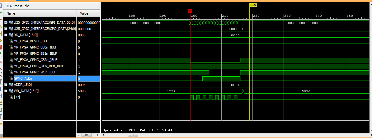
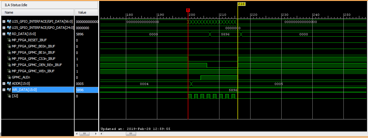
We are trying to enable the GPMC synchronous single Write / Read operation with external FPGA using NOR protocol. When we are performing write operation clock is GPMC_CLK is generating and data was written in FPGA but we cant read back the written data. But in asynchronous mode write and read operation is working fine. Please find the attached screen shorts of the wave forms captured in Vivado (FPGA chipscope) for the write ("5896" data is writing in address "4") & Read (data is reading from "5" th address) operation.
The device tree configuration is given below.
0x0 (PIN_INPUT_PULLUP | MUX_MODE0) /* gpmc_ad0.gpmc_ad0 */
0x4 (PIN_INPUT_PULLUP | MUX_MODE0) /* gpmc_ad1.gpmc_ad1 */
0x8 (PIN_INPUT_PULLUP | MUX_MODE0) /* gpmc_ad2.gpmc_ad2 */
0xc (PIN_INPUT_PULLUP | MUX_MODE0) /* gpmc_ad3.gpmc_ad3 */
0x10 (PIN_INPUT_PULLUP | MUX_MODE0) /* gpmc_ad4.gpmc_ad4 */
0x14 (PIN_INPUT_PULLUP | MUX_MODE0) /* gpmc_ad5.gpmc_ad5 */
0x18 (PIN_INPUT_PULLUP | MUX_MODE0) /* gpmc_ad6.gpmc_ad6 */
0x1c (PIN_INPUT_PULLUP | MUX_MODE0) /* gpmc_ad7.gpmc_ad7 */
0x70 (PIN_INPUT_PULLUP | MUX_MODE0) /* gpmc_wait0.gpmc_wait0 */
0x7c (PIN_OUTPUT | MUX_MODE0) /* gpmc_csn0.gpmc_csn0 */
0x90 (PIN_OUTPUT | MUX_MODE0) /* gpmc_advn_ale.gpmc_advn_ale */
0x94 (PIN_OUTPUT | MUX_MODE0) /* gpmc_oen_ren.gpmc_oen_ren */
0x98 (PIN_OUTPUT | MUX_MODE0) /* gpmc_wen.gpmc_wen */
0x9c (PIN_OUTPUT | MUX_MODE0) /* gpmc_be0n_cle.gpmc_be0n_cle */
0x88 (PIN_OUTPUT | MUX_MODE0) /* (T13) gpmc_csn3.gpmc_csn3 */
0x24 (PIN_INPUT_PULLUP | MUX_MODE0) /* gpmc_ad9.gpmc_ad9 */
0x28 (PIN_INPUT_PULLUP | MUX_MODE0) /* gpmc_ad10.gpmc_ad10 */
0x2c (PIN_INPUT_PULLUP | MUX_MODE0) /* gpmc_ad11.gpmc_ad11 */
0x30 (PIN_INPUT_PULLUP | MUX_MODE0) /* gpmc_ad12.gpmc_ad12 */
0x34 (PIN_INPUT_PULLUP | MUX_MODE0) /* gpmc_ad13.gpmc_ad13 */
0x38 (PIN_INPUT_PULLUP | MUX_MODE0) /* gpmc_ad14.gpmc_ad14 */
0x3c (PIN_INPUT_PULLUP | MUX_MODE0) /* gpmc_ad15.gpmc_ad15 */
0x74 (PIN_OUTPUT | MUX_MODE2) /* gpmc_csn0.gpmc_csn0 */
0x78 (PIN_OUTPUT | MUX_MODE0) /* (U18) gpmc_be1n.gpmc_be1n */ /* Added for FPGA */
0x8c (PIN_OUTPUT | MUX_MODE0) /* (V12) gpmc_clk.gpmc_clk */
ram@3,0 {
reg = <3 0x00000000 0x01000000>;
bank-width = <2>;
gpmc,mux-add-data = <2>;
gpmc,device-width = <2>; /* 16-bit devices */
gpmc,sync-read;
gpmc,sync-write;
gpmc,clk-activation-ns = <0>;
gpmc,sync-clk-ps = <0>; /* Minimum clock period for synchronous mode, in picoseconds */
gpmc,wait-on-read = "true";
gpmc,cs-on-ns = <0>;
gpmc,cs-rd-off-ns = <80>;
gpmc,cs-wr-off-ns = <80>;
gpmc,adv-on-ns = <0>;
gpmc,adv-rd-off-ns = <20>;
gpmc,adv-wr-off-ns = <20>;
gpmc,oe-on-ns = <30>;
gpmc,oe-off-ns = <80>;
gpmc,we-on-ns = <30>;
gpmc,we-off-ns = <80>;
gpmc,rd-cycle-ns = <80>;
gpmc,wr-cycle-ns = <80>;
gpmc,access-ns = <80>;
gpmc,page-burst-access-ns = <0>;
gpmc,cycle2cycle-samecsen;
gpmc,cycle2cycle-delay-ns = <0>;
gpmc,wr-data-mux-bus-ns = <30>;
gpmc,wr-access-ns = <80>;
};
In technical reference manual, the GPMC clock pin configuration is mentioned in section 7.1.3.3.9.6 like below.
" When the GPMC is configured for synchronous mode, the GPMC_CLK signal (which is an output)
must also be set as an input in the Pin Mux configuration for the pin. GPMC_CLK is looped back
through the output and input buffers of the corresponding GPMC_CLK pad at the device boundary.
The looped-back clock is used to synchronize the sampling of the memory signals."
How do I configure the clock pin as both output & input ? Currently I have configured as output. Whether I have change the clock pin configuration from output to input in device tree ?
thanks
Mobin P K
Write:
Read:


