This thread has been locked.

If you have a related question, please click the "Ask a related question" button in the top right corner. The newly created question will be automatically linked to this question.

RTOS/PROCESSOR-SDK-AM437X: Driving GPIO on the custom board

Part Number: PROCESSOR-SDK-AM437X
Other Parts Discussed in Thread: TLK105, TLK106

Tool/software: TI-RTOS

Dear TI team,

I need to verify the HW design of the custom board which is something between IDK_AM437x and EVM_AM437x. I also have the original IDK_AM437x board for the reference.

I can run the EtherCAT slave on the original IDK_AM437x board and it works flawlessly. The IDK_AM437x has TLK105 but my board has TLK106, I got both specs and I found no difference in pinout or registers, so I suppose there should be no SW changes related to TLK105/106.

On my custom HW among other changes I have these:

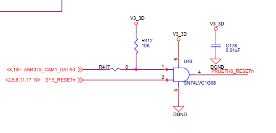
1) 3x pins are used in output to reset each PHY independently:

                Pin T22, to reset the MII1 PHY

                Pin T21, to reset the PRU0 PHY

                Pin T20, to reset the PRU1 PHY

2) We add 4x debug leds.  They are connected respectively on B5, A5, B6 and A6.  

As I see from the schematics on the IDK board only Pin 20 is used for the reset

in the C:\ti\PRU-ICSS-EtherCAT_Slave_01.00.07.02\examples\board\idkAM437x\board_phy.c I see this code:

    /*PRUETH0_RESETn */
    PhyResetInfo[0].pin = 20;
    PhyResetInfo[0].baseAddr = SOC_GPIO4_REG;
...
    GPIOModuleEnable(PhyResetInfo[0].baseAddr);
    GPIODirModeSet(PhyResetInfo[0].baseAddr, PhyResetInfo[0].pin, GPIO_DIR_OUTPUT);

    GPIOPinWrite(PhyResetInfo[0].baseAddr, PhyResetInfo[0].pin, GPIO_PIN_LOW);
    Board_delay(1000);

    GPIOPinWrite(PhyResetInfo[0].baseAddr, PhyResetInfo[0].pin, GPIO_PIN_HIGH);
    Board_delay(100000);

But as I need to set to TRUE all three pins, I try to modify the code this way:

/*PRUETH0_RESETn */
    PhyResetInfo[0].pin = 20;
    PhyResetInfo[0].baseAddr = SOC_GPIO4_REG;
/*PRUETH1_RESETn */
    PhyResetInfo[1].pin = 21;
    PhyResetInfo[1].baseAddr = SOC_GPIO4_REG;
    /*MII1_RESETn */
    PhyResetInfo[2].pin = 22;
    PhyResetInfo[2].baseAddr = SOC_GPIO4_REG;

And then...

    for (i = 0; i < (sizeof(PhyResetInfo)/sizeof(PhyResetInfo[0])); i++)
    {
        GPIOModuleEnable(PhyResetInfo[i].baseAddr);
        GPIODirModeSet(PhyResetInfo[i].baseAddr, PhyResetInfo[i].pin, GPIO_DIR_OUTPUT);

        GPIOPinWrite(PhyResetInfo[i].baseAddr, PhyResetInfo[i].pin, GPIO_PIN_LOW);
        Board_delay(1000);

        GPIOPinWrite(PhyResetInfo[i].baseAddr, PhyResetInfo[i].pin, GPIO_PIN_HIGH);
        Board_delay(100000);
    }

EtherCAT is NOT working on the custom board. I see that one port is activated (not the one I need for the ECAT) but others are not. When I connect cables to my laptop I don't see that ports are active. 

I used the offline PinMux tool to describe the pins but I found no clear example how to use files "am43xx_pinmux.h" and "am43xx_pinmux_data.c" in my program.

How can I understand that pin T20 belongs to SOC_GPIO4_REG group? Where do belong A5, B5, A6, B6?

I see that function GPIOPinWrite() is used to control the GPIO:

void GPIOPinWrite(uint32_t baseAdd,
                               uint32_t pinNumber,
                               uint32_t pinValue);

But how do I know the base address?

How do I know to which base address belongs any my pin?

I see that in the EtherCAT slave example these base addresses are used:

#define SOC_GPIO0_REG (0x44e07000U)

#define SOC_GPIO1_REG (0x4804c000U)
#define SOC_GPIO2_REG (0x481ac000U)
#define SOC_GPIO3_REG (0x481ae000U)
#define SOC_GPIO4_REG (0x48320000U)
#define SOC_GPIO5_REG (0x48322000U)

Where do these numbers come from?

I will be very grateful for any help as I'm really stuck with this task. Seemed like a simple task, but lack of understanding of how to control GPIO blocks me from get things done.

Any help will be very appreciated!

  • During the passed several days I did a little bit of research and I can answer some of my questions:
    1. Pinmux generated sources and headers are placed here:
    C:\ti\pdk_am437x_1_0_14\packages\ti\starterware\board\am43xx\
    It is necessary to take one board as a reference, or change it to your needs:
    am43xx_gpevm.c
    am43xx_gpevm.h
    am43xx_gpevm_pinmux_data.c

    The problem now - I can't find how to rebuild these sources.

    When I touch these files (update the timestamp) for example for the "evmAM437x" board and then I rebuild my project for this board, I don't see that "am43xx_gpevm_pinmux_data.c" is recompiled.

    Any help how to apply changes in "am43xx_gpevm_pinmux_data.c" to be used my project will be appreciated.

    Also I think it makes sense to PULL UP pins T20, T21 and T22 so by default they will be HIGH (1) and I don't need to control them explicitely. Am I right?

    Any help will be highly appreciated!
  • Oleg,

    I am not familiar with the Ethercat slave code that you have posted here but let me comment on device related issues and loop in the Industrial protocol expert to consult on this issue.

    Oleg Osovitskiy said:

    #define SOC_GPIO0_REG (0x44e07000U)

    #define SOC_GPIO1_REG (0x4804c000U)
    #define SOC_GPIO2_REG (0x481ac000U)
    #define SOC_GPIO3_REG (0x481ae000U)
    #define SOC_GPIO4_REG (0x48320000U)
    #define SOC_GPIO5_REG (0x48322000U)

    -> These values come from AM437x Technical reference manual (TRM). For example the GPIO0 base address comes from the L4_WKUP Memory map :

    Since you are trying to write to GPIO Pin on bank4 , you should use the base address 0x48320000.

    As far as determining which pin belongs to which group, please refer to the device datasheet. Table 4-10 describes pin attributes. In the table you will see the assignments for each pin:

    If you use the pinmux tool, the tool allows you to make pin assignments in addition to setting up the mux for the pins that you want to use. I hope the above information gives you an idea about how to go about configuring the additional pins that you have used on the custom board.

    For PHY and Ethercat configuration, I have looped in the ethercat expert and you should hear from them soon.

    Regards,

    Rahul

  • Thank you Rahul!

    Very useful information!
    I was looking in the AM437x datasheet and completely ignored TRM. My bad!
    Could you point me to the information how to rebuild sources with the new pins defined? My custom board is very similar to evmAM437x, so I'm thinking to bring new pins and rebuild the sources.

    The long term solution will be to add my custom board additionally to "evmAM437x", "idkAM437x" and "skAM437x". will be something like "customAM437x". But I need a quick proof of concept before we invest our time to do it right.
  • Hello again Rahul,

    It seems that your post was eye-opening for me.

    As I see in EtherCAT demo the reset pin is set this way:

        /*PRUETH0_RESETn */
        PhyResetInfo[0].pin = 20;
        PhyResetInfo[0].baseAddr = SOC_GPIO4_REG;
    

    So that means it is GPIO4_20. In the AM437x datasheet we look for GPIO4_20:


    In the IDK schematics I see that it is exactly AD23 is used for reset:

    So it is not T20 used on IDK used to reset PRU as I thought before, it is AD23.


  • Oleg,

    The general instructions to update pinmux and rebuilding board for Processor SDK RTOS is provided here:

    The instructions are however more specific to newer devices  that don`t use starterware baseline, so I would recommend looking at the following document that I share with customer trying to port TI SDK to custom platform.

    5432.AM335x_AMIC110_Board_Porting_using_PRSDK.pdf

    Please note that this document applies to users porting the baseline Processor SDK RTOS. If you are using some board package from Ethercat slave package then this needs to be updates using the board in that package

    Hope this helps.

    Regards,

    Rahul

  • Thank you very much Rahul!
    Your help was precious! I mark this thread as solved!