Part Number: AM5718
Other Parts Discussed in Thread: AM5728, BEAGLEBOARD-X15, TLV320AIC3104, TLV320AIC3106
I have some question regarding the audio codec (TLV320AIC3106) interfacing .
My configuration is
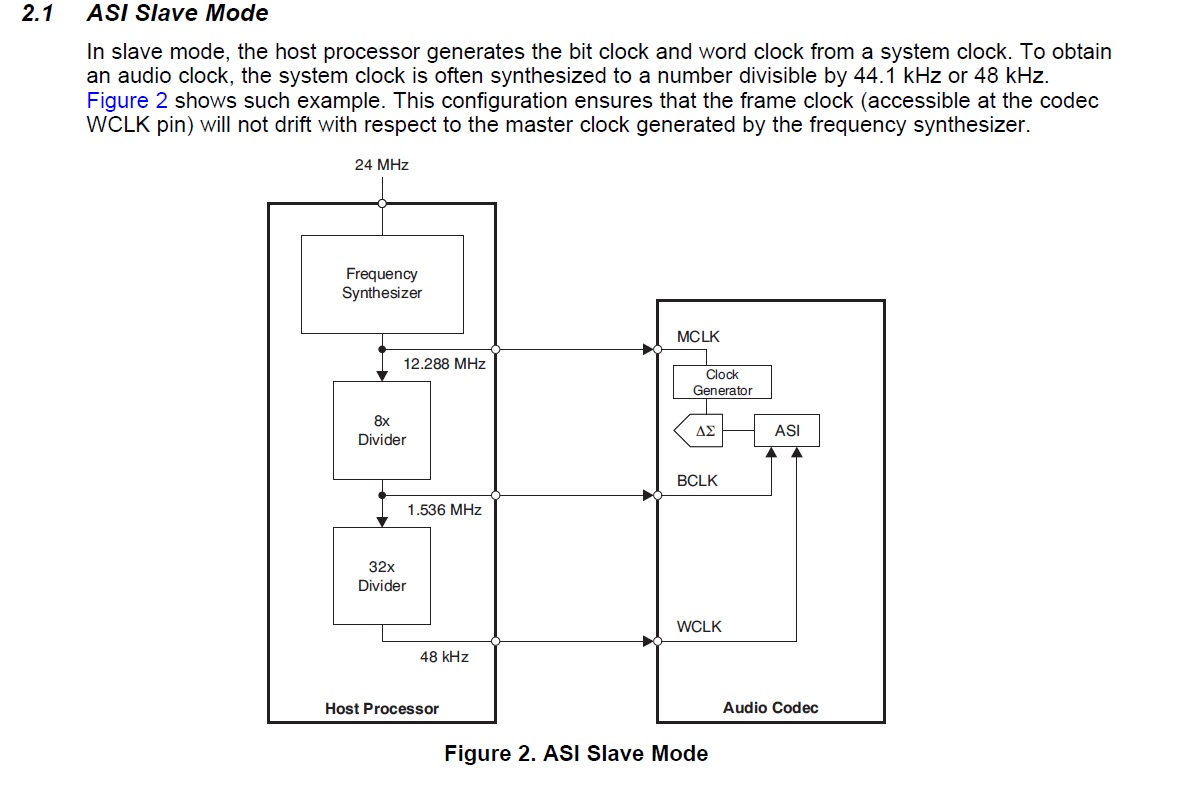
system clock 1=20MHz
system clock2 = 24.576MHz(externally feeds with generator)
clockout2----->codec MCLK(12.288MHz)
McASP3 as Master and codec as slave(Both bit clock and frame sync)
Frame sync =48KHz
bitclock = 48KHz*2*32=3.072MHz
I have created a custom design similar to AM5728-GP-EVM . No clock at CLOCKOUT2 through DTS.
my dts file is depicted below
sound0: sound0 {
compatible = "simple-audio-card";
simple-audio-card,name = "BeagleBoard-X15";
simple-audio-card,widgets =
"Line", "Line Out",
"Line", "Line In";
simple-audio-card,routing =
"Line Out", "LLOUT",
"Line Out", "RLOUT",
"MIC2L", "Line In",
"MIC2R", "Line In";
simple-audio-card,format = "dsp_b";
simple-audio-card,bitclock-master = <&sound0_master>;
simple-audio-card,frame-master = <&sound0_master>;
simple-audio-card,bitclock-inversion;
simple-audio-card,cpu {
sound-dai = <&mcasp3>;
};
sound0_master: simple-audio-card,codec {
sound-dai = <&tlv320aic3106>;
clocks = <&clkout2_clk>;
};
};
tlv320aic3106: tlv320aic3106@18 {
#sound-dai-cells = <0>;
compatible = "ti,tlv320aic3106";
reg = <0x18>;
assigned-clocks = <&clkoutmux2_clk_mux>;
assigned-clock-parents = <&sys_clk2_dclk_div>;
status = "okay";
adc-settle-ms = <40>;
AVDD-supply = <&vdd_3v3>; //vdd_3v3 v3_3d
IOVDD-supply = <&vdd_3v3>;
DRVDD-supply = <&vdd_3v3>;
DVDD-supply = <&aic_dvdd>; //aic_dvdd ldo2_reg
};
With this device node i can update
CM_CLKSEL_CLKOUTMUX2 (0x4AE06160) to 0x1
But I cannot update CM_COREAON_CLKOUTMUX2_CLKCTRL
I have gone through the following document
http://processors.wiki.ti.com/index.php/Sitara_Linux_Audio_DAC_Example
Interfacing DRA7xx Audio to Analog Codecs
I have some question
1) For integrating TLV320AIC3106 with AM5718 ,is there any kernel source modification is needed(davinci-evm.c,davinci-mcasp.c) as mentioned in the document.
2) SDK contain one defconfig file for all these board,porting instruction given in the SDK linux documentation will work without any kernel source modification.If any correction in my thought,pl z clarify.
2)with device tree,How can I configure McSAP as Master and codec as slave, and bit clock as 3.072MHz,Frame sync =48KHz.
Please help
Regards
Satheesh Kumar S
/*
 * Copyright (C) 2015-2016 Texas Instruments Incorporated - http://www.ti.com/
 *
 * This program is free software; you can redistribute it and/or modify
 * it under the terms of the GNU General Public License version 2 as
 * published by the Free Software Foundation.
 */
/dts-v1/;

#include "am571x-idk-common.dtsi"

/ {
	model = "TI AM5718 IDK";

	aliases {
		ethernet4 = &pruss1_emac0;
		ethernet5 = &pruss1_emac1;
	};

	/* Dual mac ethernet application node on icss2 */
	pruss1_eth: pruss1_eth {
		status = "disable";
		compatible = "ti,am57-prueth";
		prus = <&pru1_0>, <&pru1_1>;
		firmware-name = "ti-pruss/am57xx-pru0-prueth-fw.elf",
				"ti-pruss/am57xx-pru1-prueth-fw.elf";
		ti,pruss-gp-mux-sel = <0>,	/* GP, default */
				      <4>;	/* MII2, needed for PRUSS1_MII1 */
		sram = <&ocmcram1>;
		interrupt-parent = <&pruss1_intc>;
		interrupts = <20>, <21>;
		interrupt-names = "rx_red_hp", "rx_red_lp";

		pruss1_emac0: ethernet-mii0 {
			phy-handle = <&pruss1_eth0_phy>;
			phy-mode = "mii";
			interrupts = <20>, <22>, <23>, <26>;
			interrupt-names = "rx", "tx", "hsrprp_ptp_tx",
					  "emac_ptp_tx";
			/* Filled in by bootloader */
			local-mac-address = [00 00 00 00 00 00];
		};

		pruss1_emac1: ethernet-mii1 {
			phy-handle = <&pruss1_eth1_phy>;
			phy-mode = "mii";
			interrupts = <21>, <23>, <24>, <27>;
			interrupt-names = "rx", "tx", "hsrprp_ptp_tx",
					  "emac_ptp_tx";
			/* Filled in by bootloader */
			local-mac-address = [00 00 00 00 00 00];
		};
	};
	sound0: sound0 {
		compatible = "simple-audio-card";
		simple-audio-card,name = "BeagleBoard-X15";
		simple-audio-card,widgets =
			"Line", "Line Out",
			"Line", "Line In";
		simple-audio-card,routing =
			"Line Out",	"LLOUT",
			"Line Out",	"RLOUT",
			"MIC2L",	"Line In",
			"MIC2R",	"Line In";
		simple-audio-card,format = "dsp_b";
		simple-audio-card,bitclock-master = <&sound0_master>;
		simple-audio-card,frame-master = <&sound0_master>;
		simple-audio-card,bitclock-inversion;

		simple-audio-card,cpu {
			sound-dai = <&mcasp3>;
		};

		sound0_master: simple-audio-card,codec {
			sound-dai = <&tlv320aic3106>;

			clocks = <&clkout2_clk>;
		};
	};

};

&pruss1_mdio {
	status = "disable";
	reset-gpios = <&gpio5 8 GPIO_ACTIVE_LOW>;
	reset-delay-us = <2>;   /* PHY datasheet states 1uS min */
	pruss1_eth0_phy: ethernet-phy@0 {
		reg = <0>;
		interrupt-parent = <&gpio3>;
		interrupts = <28 IRQ_TYPE_EDGE_FALLING>;
	};

	pruss1_eth1_phy: ethernet-phy@1 {
		reg = <1>;
		interrupt-parent = <&gpio3>;
		interrupts = <29 IRQ_TYPE_EDGE_FALLING>;
	};
};

&pruss2_eth {
	ti,pruss-gp-mux-sel = <4>,	/* MII2, needed for PRUSS1_MII0 */
			      <4>;	/* MII2, needed for PRUSS1_MII1 */
};
&mcasp3 {
	#sound-dai-cells = <0>;
	assigned-clocks = <&mcasp3_ahclkx_mux>;
	assigned-clock-parents = <&sys_clkin2>;
	status = "okay";

	op-mode = <0>;	/* MCASP_IIS_MODE */
	tdm-slots = <2>;
	/* 4 serializers */
	serial-dir = <	/* 0: INACTIVE, 1: TX, 2: RX */
		1 2 0 0
	>;
	tx-num-evt = <32>;
	rx-num-evt = <32>;
};

#include "am57xx-evm-cmem-am571x.dtsi"
/*
* Copyright (C) 2015-2016 Texas Instruments Incorporated - http://www.ti.com/
*
* This program is free software; you can redistribute it and/or modify
* it under the terms of the GNU General Public License version 2 as
* published by the Free Software Foundation.
*/
#include "am57xx-industrial-grade.dtsi"
/ {
aliases {
rtc0 = &tps659038_rtc;
rtc1 = &rtc;
display0 = &hdmi0;
ethernet2 = &pruss2_emac0;
ethernet3 = &pruss2_emac1;
};
chosen {
stdout-path = &uart3;
};
vmain: fixedregulator-vmain {
compatible = "regulator-fixed";
regulator-name = "VMAIN";
regulator-min-microvolt = <5000000>;
regulator-max-microvolt = <5000000>;
regulator-always-on;
regulator-boot-on;
};
v3_3d: fixedregulator-v3_3d {
compatible = "regulator-fixed";
regulator-name = "V3_3D";
vin-supply = <&smps9_reg>;
regulator-min-microvolt = <3300000>;
regulator-max-microvolt = <3300000>;
regulator-always-on;
regulator-boot-on;
};
vtt_fixed: fixedregulator-vtt {
/* TPS51200 */
compatible = "regulator-fixed";
regulator-name = "vtt_fixed";
vin-supply = <&v3_3d>;
regulator-min-microvolt = <3300000>;
regulator-max-microvolt = <3300000>;
regulator-always-on;
regulator-boot-on;
};
vdd_3v3: fixedregulator-vdd_3v3 {
compatible = "regulator-fixed";
regulator-name = "vdd_3v3";
vin-supply = <®en1>;
regulator-min-microvolt = <3300000>;
regulator-max-microvolt = <3300000>;
};
aic_dvdd: fixedregulator-aic_dvdd {
compatible = "regulator-fixed";
regulator-name = "aic_dvdd_fixed";
vin-supply = <&vdd_3v3>;
regulator-min-microvolt = <1800000>;
regulator-max-microvolt = <1800000>;
};
src_clk_x1: src_clk_x1 {
#clock-cells = <0>;
compatible = "fixed-clock";
clock-frequency = <20000000>;
};
leds-iio {
status = "disabled";
compatible = "gpio-leds";
led-out0 {
label = "out0";
gpios = <&tpic2810 0 GPIO_ACTIVE_HIGH>;
default-state = "off";
};
led-out1 {
label = "out1";
gpios = <&tpic2810 1 GPIO_ACTIVE_HIGH>;
default-state = "off";
};
led-out2 {
label = "out2";
gpios = <&tpic2810 2 GPIO_ACTIVE_HIGH>;
default-state = "off";
};
led-out3 {
label = "out3";
gpios = <&tpic2810 3 GPIO_ACTIVE_HIGH>;
default-state = "off";
};
led-out4 {
label = "out4";
gpios = <&tpic2810 4 GPIO_ACTIVE_HIGH>;
default-state = "off";
};
led-out5 {
label = "out5";
gpios = <&tpic2810 5 GPIO_ACTIVE_HIGH>;
default-state = "off";
};
led-out6 {
label = "out6";
gpios = <&tpic2810 6 GPIO_ACTIVE_HIGH>;
default-state = "off";
};
led-out7 {
label = "out7";
gpios = <&tpic2810 7 GPIO_ACTIVE_HIGH>;
default-state = "off";
};
};
hdmi0: connector@0 {
compatible = "hdmi-connector";
label = "hdmi";
type = "a";
port {
hdmi_connector_in: endpoint {
remote-endpoint = <&tpd12s015_out>;
};
};
};
tpd12s015: encoder@0 {
compatible = "ti,tpd12s016", "ti,tpd12s015";
gpios = <0>, /* optional CT_CP_HPD */
<0>, /* optional LS_OE */
<&gpio7 12 GPIO_ACTIVE_HIGH>; /* HPD */
ports {
#address-cells = <1>;
#size-cells = <0>;
port@0 {
reg = <0>;
tpd12s015_in: endpoint@0 {
remote-endpoint = <&hdmi_out>;
};
};
port@1 {
reg = <1>;
tpd12s015_out: endpoint@0 {
remote-endpoint = <&hdmi_connector_in>;
};
};
};
};
src_clk_x1: src_clk_x1 {
#clock-cells = <0>;
compatible = "fixed-clock";
clock-frequency = <20000000>;
};
/* Dual-MAC Ethernet application node on PRU-ICSS2 */
pruss2_eth: pruss2_eth {
compatible = "ti,am57-prueth";
prus = <&pru2_0>, <&pru2_1>;
firmware-name = "ti-pruss/am57xx-pru0-prueth-fw.elf",
"ti-pruss/am57xx-pru1-prueth-fw.elf";
sram = <&ocmcram1>;
interrupt-parent = <&pruss2_intc>;
interrupts = <20>, <21>;
interrupt-names = "rx_red_hp", "rx_red_lp";
pruss2_emac0: ethernet-mii0 {
phy-handle = <&pruss2_eth0_phy>;
phy-mode = "mii";
interrupts = <20>, <22>, <23>, <26>;
interrupt-names = "rx", "tx", "hsrprp_ptp_tx",
"emac_ptp_tx";
/* Filled in by bootloader */
local-mac-address = [00 00 00 00 00 00];
};
pruss2_emac1: ethernet-mii1 {
phy-handle = <&pruss2_eth1_phy>;
phy-mode = "mii";
interrupts = <21>, <23>, <24>, <27>;
interrupt-names = "rx", "tx", "hsrprp_ptp_tx",
"emac_ptp_tx";
/* Filled in by bootloader */
local-mac-address = [00 00 00 00 00 00];
};
};
ptp_bc: ptp_bc {
compatible = "ti,am57-bc";
status = "disabled";
};
};
&dra7_pmx_core {
dcan1_pins_default: dcan1_pins_default {
pinctrl-single,pins = <
DRA7XX_CORE_IOPAD(0x37d0, PIN_OUTPUT_PULLUP | MUX_MODE0) /* dcan1_tx */
DRA7XX_CORE_IOPAD(0x37d4, PIN_INPUT_PULLUP | MUX_MODE0) /* dcan1_rx */
>;
};
dcan1_pins_sleep: dcan1_pins_sleep {
pinctrl-single,pins = <
DRA7XX_CORE_IOPAD(0x37d0, MUX_MODE15 | PULL_UP) /* dcan1_tx.off */
DRA7XX_CORE_IOPAD(0x37d4, MUX_MODE15 | PULL_UP) /* dcan1_rx.off */
>;
};
};
&i2c1 {
status = "okay";
clock-frequency = <400000>;
tps659038: tps659038@58 {
compatible = "ti,tps659038";
reg = <0x58>;
interrupts-extended = <&gpio6 16 IRQ_TYPE_LEVEL_HIGH
&dra7_pmx_core 0x418>;
#interrupt-cells = <2>;
interrupt-controller;
ti,system-power-controller;
ti,palmas-override-powerhold;
tps659038_pmic {
compatible = "ti,tps659038-pmic";
smps12-in-supply = <&vmain>;
smps3-in-supply = <&vmain>;
smps45-in-supply = <&vmain>;
smps6-in-supply = <&vmain>;
smps7-in-supply = <&vmain>;
smps8-in-supply = <&vmain>;
smps9-in-supply = <&vmain>;
ldo1-in-supply = <&vmain>;
ldo2-in-supply = <&vmain>;
ldo3-in-supply = <&vmain>;
ldo4-in-supply = <&vmain>;
ldo9-in-supply = <&vmain>;
ldoln-in-supply = <&vmain>;
ldousb-in-supply = <&vmain>;
ldortc-in-supply = <&vmain>;
regulators {
smps12_reg: smps12 {
/* VDD_MPU */
regulator-name = "smps12";
regulator-min-microvolt = <850000>;
regulator-max-microvolt = <1250000>;
regulator-always-on;
regulator-boot-on;
};
smps3_reg: smps3 {
/* VDD_DDR EMIF1 EMIF2 */
regulator-name = "smps3";
regulator-min-microvolt = <1350000>;
regulator-max-microvolt = <1350000>;
regulator-always-on;
regulator-boot-on;
};
smps45_reg: smps45 {
/* VDD_DSPEVE on AM572 */
/* VDD_IVA + VDD_DSP on AM571 */
regulator-name = "smps45";
regulator-min-microvolt = <850000>;
regulator-max-microvolt = <1250000>;
regulator-always-on;
regulator-boot-on;
};
smps6_reg: smps6 {
/* VDD_GPU */
regulator-name = "smps6";
regulator-min-microvolt = <850000>;
regulator-max-microvolt = <1250000>;
regulator-always-on;
regulator-boot-on;
};
smps7_reg: smps7 {
/* VDD_CORE */
regulator-name = "smps7";
regulator-min-microvolt = <850000>;
regulator-max-microvolt = <1150000>;
regulator-always-on;
regulator-boot-on;
};
smps8_reg: smps8 {
/* 5728 - VDD_IVAHD */
/* 5718 - N.C. test point */
regulator-name = "smps8";
};
smps9_reg: smps9 {
/* VDD_3_3D */
regulator-name = "smps9";
regulator-min-microvolt = <3300000>;
regulator-max-microvolt = <3300000>;
regulator-always-on;
regulator-boot-on;
};
ldo1_reg: ldo1 {
/* VDDSHV8 - VSDMMC */
/* NOTE: on rev 1.3a, data supply */
regulator-name = "ldo1";
regulator-min-microvolt = <1800000>;
regulator-max-microvolt = <3300000>;
regulator-boot-on;
regulator-always-on;
};
ldo2_reg: ldo2 {
/* VDDSH18V */
regulator-name = "ldo2";
regulator-min-microvolt = <1800000>;
regulator-max-microvolt = <1800000>;
regulator-always-on;
regulator-boot-on;
};
ldo3_reg: ldo3 {
/* R1.3a 572x V1_8PHY_LDO3: USB, SATA */
regulator-name = "ldo3";
regulator-min-microvolt = <1800000>;
regulator-max-microvolt = <1800000>;
regulator-always-on;
regulator-boot-on;
};
ldo4_reg: ldo4 {
/* R1.3a 572x V1_8PHY_LDO4: PCIE, HDMI*/
regulator-name = "ldo4";
regulator-min-microvolt = <1800000>;
regulator-max-microvolt = <1800000>;
regulator-always-on;
regulator-boot-on;
};
/* LDO5-8 unused */
ldo9_reg: ldo9 {
/* VDD_RTC */
regulator-name = "ldo9";
regulator-min-microvolt = <840000>;
regulator-max-microvolt = <1160000>;
regulator-always-on;
regulator-boot-on;
};
ldoln_reg: ldoln {
/* VDDA_1V8_PLL */
regulator-name = "ldoln";
regulator-min-microvolt = <1800000>;
regulator-max-microvolt = <1800000>;
regulator-always-on;
regulator-boot-on;
};
ldousb_reg: ldousb {
/* VDDA_3V_USB: VDDA_USBHS33 */
regulator-name = "ldousb";
regulator-min-microvolt = <3300000>;
regulator-max-microvolt = <3300000>;
regulator-always-on;
regulator-boot-on;
};
ldortc_reg: ldortc {
/* VDDA_RTC */
regulator-name = "ldortc";
regulator-min-microvolt = <1800000>;
regulator-max-microvolt = <1800000>;
regulator-always-on;
regulator-boot-on;
};
regen1: regen1 {
/* VDD_3V3_ON */
regulator-name = "regen1";
regulator-boot-on;
regulator-always-on;
};
regen2: regen2 {
/* Needed for PMIC internal resource */
regulator-name = "regen2";
regulator-boot-on;
regulator-always-on;
};
};
};
tps659038_rtc: tps659038_rtc {
compatible = "ti,palmas-rtc";
interrupt-parent = <&tps659038>;
interrupts = <8 IRQ_TYPE_EDGE_FALLING>;
wakeup-source;
};
tps659038_pwr_button: tps659038_pwr_button {
compatible = "ti,palmas-pwrbutton";
interrupt-parent = <&tps659038>;
interrupts = <1 IRQ_TYPE_EDGE_FALLING>;
wakeup-source;
ti,palmas-long-press-seconds = <12>;
};
tps659038_gpio: tps659038_gpio {
compatible = "ti,palmas-gpio";
gpio-controller;
#gpio-cells = <2>;
};
extcon_usb2: tps659038_usb {
compatible = "ti,palmas-usb-vid";
ti,enable-vbus-detection;
ti,enable-id-detection;
/* ID & VBUS GPIOs provided in board dts */
};
};
tpic2810: tpic2810@60 {
compatible = "ti,tpic2810";
reg = <0x60>;
gpio-controller;
#gpio-cells = <2>;
};
tc358778: tc358778@0e {
compatible = "toshiba,tc358778", "toshiba,tc358768";
reg = <0x0e>;
status = "disabled";
clocks = <&src_clk_x1>;
clock-names = "refclk";
ports {
#address-cells = <1>;
#size-cells = <0>;
port@0 {
reg = <0>;
tc358778_in: endpoint {
remote-endpoint = <&dpi_out>;
data-lines = <24>;
};
};
port@1 {
reg = <1>;
tc358778_out: endpoint {
/*
* lanes and remote-endpoint defined per
* panel.
*/
};
};
};
};
ov2659: ov2659@30 {
compatible = "ovti,ov2659";
reg = <0x30>;
clocks = <&src_clk_x1>;
clock-names = "xvclk";
pwrdn-gpios = <&gpio6 14 GPIO_ACTIVE_LOW>;
port {
ov2659_1: endpoint {
hsync-active = <1>;
vsync-active = <1>;
pclk-sample = <1>;
link-frequencies = /bits/ 64 <70000000>;
};
};
};
tlv320aic3106: tlv320aic3106@18 {
#sound-dai-cells = <0>;
compatible = "ti,tlv320aic3106";
reg = <0x18>;
assigned-clocks = <&clkoutmux2_clk_mux>;
assigned-clock-parents = <&sys_clk2_dclk_div>;
status = "okay";
adc-settle-ms = <40>;
AVDD-supply = <&vdd_3v3>; //vdd_3v3 v3_3d
IOVDD-supply = <&vdd_3v3>;
DRVDD-supply = <&vdd_3v3>;
DVDD-supply = <&aic_dvdd>; //aic_dvdd ldo2_reg
};
};
&mcspi3 {
status = "okay";
ti,pindir-d0-out-d1-in;
sn65hvs882: sn65hvs882@0 {
compatible = "pisosr-gpio";
gpio-controller;
#gpio-cells = <2>;
reg = <0>;
spi-max-frequency = <1000000>;
spi-cpol;
};
};
&uart3 {
status = "okay";
interrupts-extended = <&crossbar_mpu GIC_SPI 69 IRQ_TYPE_LEVEL_HIGH
&dra7_pmx_core 0x248>;
};
&rtc {
status = "okay";
ext-clk-src;
};
&mac {
status = "okay";
dual_emac;
};
&cpsw_emac0 {
phy_id = <&davinci_mdio>, <0>;
phy-mode = "rgmii";
dual_emac_res_vlan = <1>;
};
&cpsw_emac1 {
phy_id = <&davinci_mdio>, <1>;
phy-mode = "rgmii";
dual_emac_res_vlan = <2>;
};
&usb2_phy1 {
phy-supply = <&ldousb_reg>;
};
&usb2_phy2 {
phy-supply = <&ldousb_reg>;
};
&usb1 {
dr_mode = "host";
};
&omap_dwc3_2 {
extcon = <&extcon_usb2>;
};
&usb2 {
extcon = <&extcon_usb2>;
dr_mode = "otg";
};
&mmc1 {
status = "okay";
vmmc-supply = <&v3_3d>;
vqmmc-supply = <&ldo1_reg>;
bus-width = <4>;
cd-gpios = <&gpio6 27 GPIO_ACTIVE_LOW>; /* gpio 219 */
};
&mmc2 {
status = "okay";
vmmc-supply = <&v3_3d>;
vqmmc-supply = <&v3_3d>;
bus-width = <8>;
non-removable;
max-frequency = <96000000>;
no-1-8-v;
};
&dcan1 {
status = "okay";
pinctrl-names = "default", "sleep", "active";
pinctrl-0 = <&dcan1_pins_sleep>;
pinctrl-1 = <&dcan1_pins_sleep>;
pinctrl-2 = <&dcan1_pins_default>;
};
&qspi {
status = "okay";
spi-max-frequency = <76800000>;
m25p80@0 {
compatible = "s25fl256s1", "jedec,spi-nor";
spi-max-frequency = <76800000>;
reg = <0>;
spi-tx-bus-width = <1>;
spi-rx-bus-width = <4>;
#address-cells = <1>;
#size-cells = <1>;
/* MTD partition table.
* The ROM checks the first four physical blocks
* for a valid file to boot and the flash here is
* 64KiB block size.
*/
partition@0 {
label = "QSPI.SPL";
reg = <0x00000000 0x000040000>;
};
partition@1 {
label = "QSPI.u-boot";
reg = <0x00040000 0x00100000>;
};
partition@2 {
label = "QSPI.u-boot-spl-os";
reg = <0x00140000 0x00080000>;
};
partition@3 {
label = "QSPI.u-boot-env";
reg = <0x001c0000 0x00010000>;
};
partition@4 {
label = "QSPI.u-boot-env.backup1";
reg = <0x001d0000 0x0010000>;
};
partition@5 {
label = "QSPI.kernel";
reg = <0x001e0000 0x0800000>;
};
partition@6 {
label = "QSPI.file-system";
reg = <0x009e0000 0x01620000>;
};
};
};
&gpu {
status = "ok";
};
&hdmi {
status = "okay";
/*
* XXX: Support AM572x-Rev 1.2a. this is wrong for AM571x-rev 1.3a,
* AM572x-Rev1.3a - but thanks to always-on, they work.
* TODO: SWITCH TO LDO4 once rev 1.2a is deprecated
* (on rev 1.3a availability)
*/
vdda-supply = <&ldo3_reg>;
port {
hdmi_out: endpoint {
remote-endpoint = <&tpd12s015_in>;
};
};
};
&dss {
status = "okay";
vdda_video-supply = <&ldoln_reg>;
ports {
#address-cells = <1>;
#size-cells = <0>;
port@0 {
reg = <0>;
dpi_out: endpoint {
remote-endpoint = <&tc358778_in>;
data-lines = <24>;
};
};
};
};
&bb2d {
status = "okay";
};
&pruss_soc_bus1 {
status = "disable";
pruss1: pruss@0 {
status = "disable";
};
};
&pruss_soc_bus2 {
status = "disable";
pruss2: pruss@0 {
status = "disable";
};
};
&pruss2_mdio {
status = "disable";
pruss2_eth0_phy: ethernet-phy@0 {
reg = <0>;
interrupt-parent = <&gpio3>;
interrupts = <30 IRQ_TYPE_EDGE_FALLING>;
};
pruss2_eth1_phy: ethernet-phy@1 {
reg = <1>;
interrupt-parent = <&gpio3>;
interrupts = <31 IRQ_TYPE_EDGE_FALLING>;
};
};
&cpu0 {
vdd-supply = <&smps12_reg>;
};