This thread has been locked.

If you have a related question, please click the "Ask a related question" button in the top right corner. The newly created question will be automatically linked to this question.

TDA4VM: Multiple cameras can only display one camera

Part Number: TDA4VM

hi ti

sdk:06_02

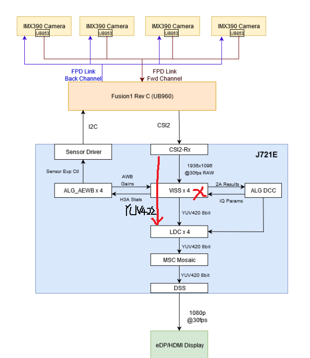
in our coustom board,i test multi cam app follow vision app app_multi_cam.

now:

1.4 cam can capture successfully,i can save 4 cam capture pictures

2.but only one cam display,other 3 cam can not display.

perhaps I need change some code in app_multi_cam.c file,anyone know it,thanks

  • Hi,

    I think you could select the camera to be displayed from the console menu. Could you please check if there is any option to select camera?

    Regards,

    Brijesh 

  • no,there are no option to select camera.

    there are only number of cameras to be enabled.

    perhaps in openvx,there are api about choose which camera to display

  • when I run vx_app_multi_cam.out,there are not option to choose camera.

    if I need change code to choose one cam?

  • Hello Brijesh

    I read a topic in https://e2e.ti.com/support/processors/f/791/t/897997?tisearch=e2e-sitesearch&keymatch=display%2520node    

    about:

    You asked "How is display not able to access all the 4 camera channels when the convertor output is just a single image object?" Internally to the display node, there is an option that checks if the given vx_image is an element of an object array.  If it is, then the node can access the full object array and use an index supplied by the user to select which index of this array to display.  If no index is provided, it defaults to the 0 index, which is the original image itself.

    i run multi cam app,there no option about chooce camera,this is my log:

    root@j7-evm:/opt/vision_apps# ./vx_app_multi_cam.out
    APP: Init ... !!!
    APP_LOG: Mapping 0xac000000 ...
    APP_LOG: Mapped 0xac000000 -> 0xffffaaaf0000 of size 262144 bytes
    MEM: Init ION ... !!!
    MEM: Initialized ION (fd=4) !!!
    MEM: Init ION ... Done !!!
    IPC: Init ... !!!
    APP_LOG: Mapping 0xac040000 ...
    APP_LOG: Mapped 0xac040000 -> 0xffffa8b50000 of size 33161216 bytes
    APP_LOG: Mapping 0x30e00000 ...
    APP_LOG: Mapped 0x30e00000 -> 0xffffaafe0000 of size 3072 bytes
    IPC: Init ... Done !!!
    REMOTE_SERVICE: Init ... !!!
    REMOTE_SERVICE: Init ... Done !!!
    APP: Init ... Done !!!
         0.006580 s:  VX_ZONE_INIT:Enabled
         0.006601 s:  VX_ZONE_ERROR:Enabled
         0.006606 s:  VX_ZONE_WARNING:Enabled
         0.007036 s:  VX_ZONE_INIT:[tivxInit:64] Initialization Done !!!
         0.007156 s:  VX_ZONE_INIT:[tivxHostInit:44] Initialization Done for HOST !!!
    ENTRY
     Multi Camera Demo - (c) Texas Instruments 2019
     ========================================================
     Usage,
      ./vx_app_multi_cam.out --cfg <config file>
    Defaulting to interactive mode
    tivxHwaLoadKernels done
    tivxImagingLoadKernels done
         0.007853 s: ISS: Enumerating sensors ... !!!
         0.008166 s: ISS: Enumerating sensors ... found 0 : IMX390-UB953_D3
         0.008172 s: ISS: Enumerating sensors ... found 1 : AR0233-UB953_MARS
         0.008177 s: ISS: Enumerating sensors ... found 2 : AR0820-UB953_LI
         0.008181 s: ISS: Enumerating sensors ... found 3 : OV10635-UB913_TN
    4 sensor(s) found
    Supported sensor list:
    a : IMX390-UB953_D3
    b : AR0233-UB953_MARS
    c : AR0820-UB953_LI
    d : OV10635-UB913_TN
    Select a sensor
    [MCU2_1]     65.927544 s: ImageSensor_RemoteServiceHandler: IM_SENSOR_CMD_CREATE
    [MCU2_1]     65.927600 s: Sensor at index 0 = IMX390-UB953_D3
    [MCU2_1]     65.927630 s: Sensor at index 1 = AR0233-UB953_MARS
    [MCU2_1]     65.927655 s: Sensor at index 2 = AR0820-UB953_LI
    [MCU2_1]     65.927678 s: Sensor at index 3 = OV10635-UB913_TN
    d
    Querying OV10635-UB913_TN
         1.071328 s: ISS: Querying sensor [OV10635-UB913_TN] ... !!!
         1.071541 s: ISS: Querying sensor [OV10635-UB913_TN] ... Done !!!
    Enable LDC? Yes:1 No: 0
    Invalid selection
    . Try again
    Enable LDC? Yes:1 No: 0
    [MCU2_1]     66.991000 s: ImageSensor_RemoteServiceHandler: IM_SENSOR_CMD_QUERY
    [MCU2_1]     66.991053 s: Received Query for OV10635-UB913_TN
    0
    Max number of cameras supported by sensor OV10635-UB913_TN = 4
    Please enter number of cameras to be enabled
    Invalid selection
    . Try again
    Max number of cameras supported by sensor OV10635-UB913_TN = 4
    Please enter number of cameras to be enabled
    4
    app_init done
    Querying OV10635-UB913_TN
         3.455045 s: ISS: Querying sensor [OV10635-UB913_TN] ... !!!
         3.455248 s: ISS: Querying sensor [OV10635-UB913_TN] ... Done !!!
    capture create
    viss & aewb create
    WDR mode is not supported. Defaulting to linear
    Sensor width = 1280
    Sensor height = 720
    Sensor DCC ID = 233
    Sensor Supported Features = 0x20
    Sensor Enabled Features = 0x20
         3.455924 s: ISS: Initializing sensor [OV10635-UB913_TN], doing IM_SENSOR_CMD_PWRON ... !!!
         3.456218 s: ISS: Initializing sensor [OV10635-UB913_TN], doing IM_SENSOR_CMD_CONFIG ... !!!
    [MCU2_1]     69.374707 s: ImageSensor_RemoteServiceHandler: IM_SENSOR_CMD_QUERY
    [MCU2_1]     69.374763 s: Received Query for OV10635-UB913_TN
    [MCU2_1]     69.375588 s: ImageSensor_RemoteServiceHandler: IM_SENSOR_CMD_PWRON
    [MCU2_1]     69.375668 s: IM_SENSOR_CMD_PWRON : channel_mask = 0xf
    [MCU2_1]     69.375878 s: ImageSensor_RemoteServiceHandler: IM_SENSOR_CMD_CONFIG
    [MCU2_1]     69.375928 s: Application requested features = 0x20
    [MCU2_1]
    [MCU2_1]     69.375991 s: ub960_cfgScript : ub960I2cAddr = 0x30
    [MCU2_1]     69.376018 s: UB960 config start
    Next content is to config sensor,then display one cam
  • Hi,

    Multi-Camera application uses mosaic node to merge and to display all 4 channels in side by side fashion, aren't you getting 2x2 mosaic display?

    Rgds,

    Brijesh

  • Hi

    Due to my sensor is yuv format.

    I disable viss,ldc,mosaic node,i only use capture and display node,i can display one cam successfully.

    in this situation,can I change cam to display?only one cam can display(other 3 cam capture picture is ok)

  • Hi,

    YUV sensor would require change in the dataflow. 

    Because VISS outputs in YUV420 format and then mosaic nodes merges them.

    But in your case, i guess the output format would be YUV422, so this requires to be converted into YUV420 first and then mosaic node can be used..

    Rgds,

    Brijesh

  • how to converted into YUV420?

  • Hi expert

    due to the output format is YUV422 in my case,i can not use mosaic node,how to converted into YUV420 in code?

    mosaic create
        23.201895 s:  VX_ZONE_ERROR:[vxSetParameterByIndex:228] Supplied value was not actually a reference
        23.201903 s:  VX_ZONE_ERROR:[vxSetParameterByIndex:307] Specified: parameter[2] type:00000000 => (nil)
        23.201909 s:  VX_ZONE_ERROR:[vxSetParameterByIndex:311] Required: parameter[2] dir:0 type:00000813
        23.201915 s:  VX_ZONE_ERROR:[vxSetReferenceName:570] vxSetReferenceName: Invalid reference
    before display create
    before pipelining setup
        23.202018 s:  VX_ZONE_ERROR:[ownReleaseReferenceInt:299] ownReleaseReferenceInt: Invalid reference
    before vxSetGraphScheduleConfig
    vxSetGraphScheduleConfig done
    [MCU2_1]     72.810555 s:  OV10635 config done
    [MCU2_1]     72.810611 s: ov10635 probe
    [MCU2_1]     72.810659 s: ov10635 address:46, read reg:300b
    [MCU2_1]     72.811580 s: value:35
    [MCU2_1]     72.811622 s: ov10635 address:46, read reg:300a
    [MCU2_1]     72.812489 s: value:a6
    [MCU2_1]     72.812534 s: OV10635_Probe SUCCESS : Read expected value 0xa6 at chip ID register 0x300a
    [MCU2_1]     72.812606 s: sensor config status:0
    [MCU2_1]     72.812629 s: IM_SENSOR_CMD_CONFIG returning status = 0
    Segmentation fault (core dumped)


  • Hi,

    The only module, which supports this conversion, is LDC. You need to include LDC node in your data path, after capture node and convert yuv422 to yuv420, then mosaic node can be used to merge channels in 2x2 format.

    Rgds,

    Brijesh

  • Hi

    I read the LDC node code,and include LDC node,i need change the code in LDC node?

    /* Allocate sample NV12 image, using which object array of NV12 would be created */
      sample_ldc_nv12_out_img = vxCreateImage(
                                    context,
                                    obj->table_width,
                                    obj->table_height,
                                    VX_DF_IMAGE_NV12);

    i need change VX_DF_IMAGE_NV12?

  • Hi,

    Yes, you need to create output image with the NV12 format for LDC.

    Rgds,

    Brijesh

  • Hi

    First,thank you for you support,now 4 cam can display together 2x2

    But there are new question=》the 2x2 cam display one minutes(short time),the app will dead(stop state)

    in app_multi_cam.c:

    1.capture node:

     obj->sample_raw_img=vxCreateImage(
                                    context,
                                    obj->table_width,
                                    obj->table_height,
                                    VX_DF_IMAGE_UYVY); =>yuv422 formate

        /* Allocate frames */
        for(buf_id=0; buf_id<NUM_BUFS; buf_id++)
        {
            obj->capt_frames[buf_id] = vxCreateObjectArray(
                                        obj->context,
                                        (vx_reference)obj->sample_raw_img,
                                        obj->num_cameras_enabled);
            if (vxGetStatus((vx_reference)obj->capt_frames[buf_id]) != VX_SUCCESS)
            {
                APP_PRINTF("obj->capt_frames[buf_id] create failed\n");
                return VX_FAILURE;
            }
            /*add by wy*/
            obj->capt_uyvy_out_img[buf_id] = (vx_image)vxGetObjectArrayItem(obj->capt_frames[buf_id], 0);
            if (vxGetStatus((vx_reference)obj->capt_uyvy_out_img[buf_id]) != VX_SUCCESS)
            {
                APP_PRINTF("capt_uyvy_out_img[buf_id] create failed\n");
                return VX_FAILURE;
            }
            /*add by wy*/
        }

    2.ldc node:

           /* Allocate sample NV12 image, using which object array of NV12 would be created */
        sample_ldc_nv12_out_img = vxCreateImage(
                                    context,
                                    obj->table_width,
                                    obj->table_height,
                                    VX_DF_IMAGE_NV12);

        obj->ldcNode = tivxVpacLdcNode(
                                obj->graph,
                                obj->ldc_param_obj,
                                NULL,
                                obj->region_params_obj,
                                obj->mesh_params_obj,
                                obj->mesh_img,
                                NULL,
                                obj->capt_uyvy_out_img[0],  =>input yuv422
                                obj->ldc_nv12_out_img[0],   =>output yuv420
                                NULL);

    3.mosaic node =>not change

    4.display node=>not change

    i do not use viss node

    do you know where the problem is?

  • Hi,

    Do you mean it runs fine for almost 3.5K frames and then becomes dead?

    Can you please check if you are calling tivxSetNodeParameterNumBufByIndex for LDC output frame?

    Please note it will be difficult to figure out from just small code snippet. If possible, please share complete graph code.

    Rgds,

    Brijesh

  • I check ldc node code,not calling tivxSetNodeParameterNumBufByIndex

    this is the app_multi_cam.c ,please help me check where the problem is?

    app_multi_cam.c

  • hello

    I have shared my app_multi_cam.c,if you have time,please help me to figure out,thank you very much 

  • hi

    I think I need show the data flow in my multi cam demo:

    in capture node:

           1.get yuv422 image from sensor directly

    in ldc node:

           1.get yuv422 image from capture node

            2.change yuv422 to yuv420

    in mosaic node

            1.get yuv420 image from ldc node to display

    in my demo,i do not use viss node.

    but the app only run short time fine then dead,i do not know why

  • HI Brijesh

    I need your help,thank you very much

    I've been bothered by question for a bit long time..

  • Hi,

    Why do you use raw image to capture yuv data? This will not configure CSIRX module correctly, if your sensor is sending out CSI stream in YUV422 format. So i believe capture itself is not working.. Could you please correct it?

        obj->sample_raw_img = vxCreateImage(obj->context,sensorParams.sensorInfo.raw_params.width, sensorParams.sensorInfo.raw_params.height,sensorParams.sensorInfo.raw_params.format[0].pixel_container);

    Rgds,

    Brijesh

  • Hi

    thank you for you response

    my sensor dataformat is VX_DF_IMAGE_UYVY

    In capture node,i use obj->sample_raw_img = vxCreateImage(obj->context,sensorParams.sensorInfo.raw_params.width, sensorParams.sensorInfo.raw_params.height, VX_DF_IMAGE_UYVY);

    in this situation,capture node is work ok and 4 cam can display in turn

    when I add mosic and ldc node to display 2x2 format,the app can only run short time.in this situation,can save 4 cam capture picture by press 's'

    and i can not use tivxCreateRawImage() function,use this function,the app can not run sussessful.

  • change tivx_raw_image sample_raw_img to vx_image sample_raw_img  (not raw img) in app_multi_cam.h

  • Hi,

    Can you please add these nodes one by one?

    Can you add LDC first and then Mosaic? Adding a LDC node after Viss should be easier. You just need to create an output image of YUV420 format and create node. no need to even provide back mapping table.. In this case, LDC will just be used to do format conversion.

    Rgsd,

    Brijesh