This thread has been locked.

If you have a related question, please click the "Ask a related question" button in the top right corner. The newly created question will be automatically linked to this question.

AM5749: GPMC_FCLK frequency

Part Number: AM5749
Other Parts Discussed in Thread: ADS8422, ADC3660,

Hi,

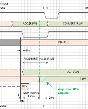
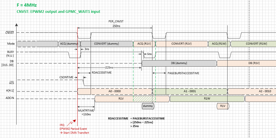
I'm currently developping the interface between the GPMC parrelle port and an ADC (ADS8422). To fit with ADC requirement, I need to set the RdAccessTime and PageBurstAccessTime parameter properly. The related time (in ns) is calculated according to a number of GPMC_FCLK cycles. But the maximum cycles of each of them do not fit with what is expexted due to the base frequency of 266MHz.

For example, the maximum cycle number of RdAccessTime is '31'. At 266MHz, the cycle delay is 3.75ns, so 31 cycles is 116.5ns. The requiered delay should be more than 550ns.

Is it possible to reduce the GPMC_FCLK from 266MHz to 50MHz? is there any prescaler into the GPMC clock domain?

Best Regards,

Sylvain

  • Sylvain PALMERI said:
    To fit with ADC requirement, I need to set the RdAccessTime and PageBurstAccessTime parameter properly. The related time (in ns) is calculated according to a number of GPMC_FCLK cycles. But the maximum cycles of each of them do not fit with what is expexted due to the base frequency of 266MHz.

    Have you considered taking the BUSY signal from the ADC and connecting to the WAIT signal of the AM57xx?

    Sylvain PALMERI said:
    For example, the maximum cycle number of RdAccessTime is '31'. At 266MHz, the cycle delay is 3.75ns, so 31 cycles is 116.5ns. The requiered delay should be more than 550ns.

    I was trying to match this delay with the ADS8422 data sheet.  I was having trouble finding it.  Can you point me to it?

    Sylvain PALMERI said:
    is there any prescaler into the GPMC clock domain?

    Please look for "TIMEPARAGRANULARITY" and "GPMCFCLKDIVIDER" in the Technical Reference Manual.  In short, if you max out both of these, you could achieve an effective /8 (33.25 MHz) on the GPMC_FCLK for those parameters.

    EDIT Feb 10, 2021: Sorry, I was mistaken on GPMCFCLKDIVIDER.  That primarily applies to the speed of the GPMC_CLK signal as derived from GPMC_FCLK.  It doesn't divide all the timings as desired.  Only TIMEPARAGRANULARITY does that.

  • Hi Brad,

    Thanks for your feedback.

    I agree for the parameter "TIMEPARAGRANULARITY" as the Page mode Successive Data maximum Access Time is defined by the formula:   PageBurstAccessTime × (TimeParaGranularity + 1).

    But "GPMCFCLKDIVIDER" is not include into the formula. For me, except if I'm wrong, this param allows the GPMC_CLK output to be devided for synchronous devices, but GPMC_FCLK is not affected.

    Maybe in synchronous mode, the timing depend on the GPMC_CLK cycle, but I cant use this mode.

    I don't read anywhere in the TRM that the timings are based on GPMC_CLK cycles, so even if I change the GPMCFCLKDIVIDER and I reach to reduce the GPMC_CLK, I don't see how it can help to increase the 

    RdAccessTime...

    I forgot to mention that I use a multiplexer in front of the ADC that give 150ns max of transition time.So even if the busy signal is connected to the WAIT input, I need to wait  150ns more before launching a new conversion. This impacts the sample rate that should be reduced to 2.5MHz, the RdAccessTime parameter for the first sample, and once the GPMC module synchronized, the PageBurstAccessTime to be sure that the next address switch when the busy signal is high.

    The GPMC EDMA read is asynchrone. The worst case is when the ADC input (ADCIN) is ready to be sampled when the ACQ mode of the ADC is over (red line). So I need to wait for the next ACQ and keep the address unchanged until the next ACQ (during busy signal high).

    For the next ACQ, due to the transition time delay, I need to release the address output when the busy signal is high. The address will automatically be kept unchanged (dash lines) until the busy goes low.

    Best regards,

    Sylvain

  • Sylvain,

    Sorry, I didn't read your response as closely as I should have since I saw you marked my answer as "verified".  You're correct that I made a mistake on GPMCFCLKDIVIDER.  You should be able to go back to my earlier response and "unresolve" it, I think.  In any case, let's just continue the discussion here.  Is it ok if I just delete the other post?

    That mux creates a lot of issues!  I'm trying to think of some solutions...

    1. You could slow down all the clocking to make the GPMC slower, but that's going to have system wide implications, so I don't really like that solution.

    2. What about using some GPIOs as the mux selector.  You could then adjust the GPIOs and then read the data.  That way the mux would be outside the GPMC timings.

    3. You could potentially write ICSS PRU code to bit-bang this interface.  You may be tight on pins though.  If the data converter supports an 8-bit mode that might be an option.

    Best regards,
    Brad

  • Hi Brad,

    Thank you for replying. I'm glad to see you again!

    Brad Griffis said:
    You should be able to go back to my earlier response and "unresolve" it, I think.  In any case, let's just continue the discussion here.  Is it ok if I just delete the other post?

    I tried many options to mark the message as "unresolved" without success. I don't know how to switch back, but we can continue here and delete the other post for sure.

    Yes! This mux is definitivly a millstone around my neck as I wast my time to find an ADC as fast as possible, and when I go deeper in the global functionnality, the result is not so good as expected. But my objective is to validate the function, and being able to capture signals from ADC in a first time. In a second time, I will optimize the timing and for sure find a faster multiplexer ^^

    Ok..

    Brad Griffis said:
    1. You could slow down all the clocking to make the GPMC slower, but that's going to have system wide implications, so I don't really like that solution.

    I would not touch the L3 clock domain as I don't know what kind of side effect it could create, and which other module it could be affected.

    Brad Griffis said:
    2. What about using some GPIOs as the mux selector.  You could then adjust the GPIOs and then read the data.  That way the mux would be outside the GPMC timings.

    That's was my first attention, but the GPIO toggles within 200ns. I wanted to change the mux address on the rising edge of the bust signal. The 150ns of transition time would have been transparent as it would have spent durint the high state of the busy signal.

    But polling the busin signal takes 200ns, toggling the IO takes 200ns and the busy stay high during the conversion that takes 225ns max. That's not compatible. That is the reason why I wanted to perform the conversion with the DMA.

    Brad Griffis said:
    3. You could potentially write ICSS PRU code to bit-bang this interface.  You may be tight on pins though.  If the data converter supports an 8-bit mode that might be an option.

    I saw this option in some posts but to be honnest I don't know where this solution lead to: The control is made by the DSP. If the data are sampled by another core, I think I will face of some delay to transmit data from the PRU. And I'm not so famillar with PRU devleppement (new RTOS project....). So I'm afraid delaying the project too much.

    Best regards,

    Sylvain.

  • Sylvain PALMERI said:
    Yes! This mux is definitivly a millstone around my neck as I wast my time to find an ADC as fast as possible, and when I go deeper in the global functionnality, the result is not so good as expected.

    How many ADC channels are you sampling?  I've struggled with high speed ADC interfaces with other customers.  The best option I've found so far is the ADC3660.  You can get two channels into the McASP at 3.125 MSPS (i.e. 6.25 MSPS in aggregate across the two channels).  That particular ADC oversamples so you can actually start with a much higher sampling rate and improve your SNR through decimation.  That also helps keep cost down on anti-aliasing filters.

    Would something like that be an option?

    Sylvain PALMERI said:
    I would not touch the L3 clock domain as I don't know what kind of side effect it could create

    I agree it's not a very desirable solution.

    Sylvain PALMERI said:
    That's was my first attention, but the GPIO toggles within 200ns. I wanted to change the mux address on the rising edge of the bust signal. The 150ns of transition time would have been transparent as it would have spent durint the high state of the busy signal.

    Just had an epiphany!  This is a combo of the gpio suggestion and the PRU suggestion.  What if you wrote some super simple code on the PRU that simply polls that BUSY pin and then increments the GPIO output?  I'm making an assumption here that you just cycle through the inputs sequentially.  Hopefully that is true.  Would something like that work?  That would avoid some of the complexities of data transfer between PRU and DSP, but still allow you to control the mux without impacting the GPMC timings.

  • PS.  In case you didn't know the PRU has local I/Os with 5ns access times, i.e. a vast improvement over the ~200ns access times you see using the CPU to access the GPIO peripheral.  

    One other thing...  I hope you're planning to use DMA to perform these reads from the GPMC.  If you're using the CPU you'll see gaps between accesses.

  • I'm afraid to not having any others choices, as I already developed the board to test the ADS8422. On the paper, it fit exactly with what I need. This board is like an eval board to connect the main board including a parallel port output (GPMC) from the AM5749. Once validated, this ADC will be integrated on the next prototype.

    I'm thinking about the idea to split the function with both DSP and PRU. I don't thing the address pins of the GPMC are shared with the PRU GPIO. But this is an excellent idea. I will check if the modification is simple.

    To answer your PS, I saw the benchmark that compare the ARM and the PRU toggling I/O. 5ns goes beyond my expectations ! Concerning the DMA, I already tested the GPMC to communicate with a FPGA eval board. I tested with and without DMA, and I agree, DMA is definitively the most efficient way to exchange data. That's why I would like to use it, so when the DMA transfer is complete, the associated interrupt will launch the control, Everything will be done automatically.

    It's a shame that's not possible to adjust the timing... That would be the best way to not modify the board which I just launch the fabrication^^

    Best regards,

    Sylvain

  • Sylvain,

    I had a quick look to see if any of the GPMC address pins overlapped with PRU pins.  It didn't look like it.  Is there any way to modify your board to make that work?  I'm assuming you'll need to spin the board -- hopefully that's possible.

    I just had one other thought come to mind.  This is admittedly half baked, but I'd like to help you avoid spinning the board if possible...  I was wondering if it might be possible to perform some type of "dummy access" to get the mux into the proper state.  For example, it doesn't even have to be a dummy read.  It could be a dummy write.  I don't recall off the top of my head what happens to the address pins between accesses.  I expect they would maintain their previous value to minimize unnecessary toggling.  That being the case, if the one and only device on the GPMC is the data converter, perhaps you could do a dummy write followed by a dummy read to get your data.

    Best regards,
    Brad

  • Hi Brad,

    The dummy write do not risk to put the GPMC data in output mode and conflict with ADC output? and increase CPU time to manage all of that manually..

    The modifications are minor, I just have to get the IO from the PRU_ICSS already used for the Ethernet. There is some 22ohms resistors that I can use to get the GPO. I think this is the best way to get the performances of the ADC. I already redraw the diagrams, and everything looks correct so far.

    Thanks a lot for your time Brad. If you want I can give you some update of my progress, but I don't know if you will be notified if the post is closed.

    Best regards,

    Sylvain.    

  • Sylvain,

    Sylvain PALMERI said:
    The dummy write do not risk to put the GPMC data in output mode and conflict with ADC output?

    I was expecting the data converter does not drive the bus when its chip select is not selected, but perhaps that's not a valid assumption.  I also made assumptions related to the behavior of the GPMC address pins between accesses.  We would need to confirm all these items before moving forward with this option.

    Sylvain PALMERI said:
    The modifications are minor, I just have to get the IO from the PRU_ICSS already used for the Ethernet. There is some 22ohms resistors that I can use to get the GPO. I think this is the best way to get the performances of the ADC. I already redraw the diagrams, and everything looks correct so far.

    The PRU method will be better from a performance perspective, so if you've found a way forward using this method, I think that is the best choice.

    Can you please tell me the precise ball numbers and mux modes you are intending to use for the PRU signals?  I wanted to briefly sanity check what you're doing. There are lots of PRU pins and modes so I didn't want there to be any confusion.

    Sylvain PALMERI said:
    Thanks a lot for your time Brad. If you want I can give you some update of my progress, but I don't know if you will be notified if the post is closed.

    I will still get notifications if you respond here.  Eventually this post will lock however and you won't be able to respond.  I don't recall the exact timeframe.

    I'm glad we were able to figure out a path forward!  Good luck on the project!  Have a good weekend,

    Best regards,
    Brad

  • Hi Brad,

    I found another idea to avoid using the PRU (and to minimize the modifications). By connecting the CNVST signal to the GPMC_WAIT (instead of the BUSY from the ADC), the impact will be as follow:

    1. The CNVST signal is generated by the EPWM2, so that I can use the Period Event to trig the GPMC read. The GPMC read will be synchronized with the conversion. That a big improvement.

    2. The address will be incremented during the previous conversion, so that the mux delay will be transparent.

    3. That allows to get the ADC performances (4MHz)

    The only inconvenient is the dummy conversion that I need to perform at the begining but regarding the gain of performances, I can deal with that!

    Here is an update of the diagram:

    Could you tell me what do you think about?

    Best regards,

    Sylvain.

  • Sylvain,

    Clever idea!  One potential concern I have is the latency to go from PWM DMA event to GPMC read.  There's going to be some amount of delay for the event to propagate from PWM to DMA, followed by delay to be processed and queued by the DMA, followed by the interconnect delay for that access to get to the GPMC and finally turn into an external access.

    On a related note, I recommend that you dedicate one of the EDMA queues to this purpose of reading the GPMC.  Those transfers will be blocked for long periods of time, so you don't want a bunch of other transfers queued up behind.  Similarly you don't want your timing-sensitive GPMC access to be queued up behind any other data transfers.

    Best regards,
    Brad

  • Hi Brad,

    I agree, these delay must be characterized. The good thing is that they are located during the wait state, so maybe I will have to adjust the pageburst and pageaccess time. I hope not having bad surprises.

    Concerning the DMA, I was hoping disabling the IRQ during the DMA transfer. Do you think there something more efficient with DMA parameter? To be honest, I'm not so familiar with DMA process. I found one way to make it working based on some examples. So there is probably some good things to know to improve the way I use it.  

    Best regards,

    Sylvain.

  • Sylvain PALMERI said:
    Concerning the DMA, I was hoping disabling the IRQ during the DMA transfer. Do you think there something more efficient with DMA parameter?

    There are 3 different EDMA controllers in the AM57xx, i.e. one in each of the two DSP subsystems as well as a chip-level controller.  I assume you'll be using the DSP's local EDMA controller.  Within the given EDMA subsystem, there is something called the "channel controller" and the "transfer controller".  At a high level, the channel controller provides you with 64 virtual channels.  The transfer controllers on the other hand provide the physical channels.  The DSP EDMA has two transfer controllers meaning it's possible for two transfers to be physically on-going at any moment.  My point was to make sure you're utilizing both of these transfer controllers, at least if you're using EDMA for anything else.  If this is the one and only DMA transfer then you don't have to worry about this.

  • Hi Brad,

    Just an update of my progress. I don't have the ADC board yet but I can test the GPMC settings.

    The synchro signal (green) reset the EPWM2 (CNVST yellow) on the rising edge, and start the DMA transfer (blue signal GPMC_CS0) on the next CNVST falling edge. The red signal show the address toggle (GPMC_A0) after the WAIT1 signal (=CNVST) is going low. It seems to work as expected so far :)

    Your doubts regarding the IRQ latency was justified. So it takes some delays between the CNVST falling edge, and the CS goes low. Here I show the 150ns needed by the mux to be sure that the ADC input is present before the acquisition mode of the ADC. To keep some margin, I decreased the sampling frequency down to 3.3MHz.

    Best regards,

    Sylvain.

  • Thanks for the update.  That all looks encouraging.

  • Hi Brad,

    Just an update. I finally reached to make the GPMC read working properly via the EDMA:

    (In blue the mux output)

    Thanks again for your support :)

    Regards,

    Sylvain.